4-4 Mx-Series Operation Manual
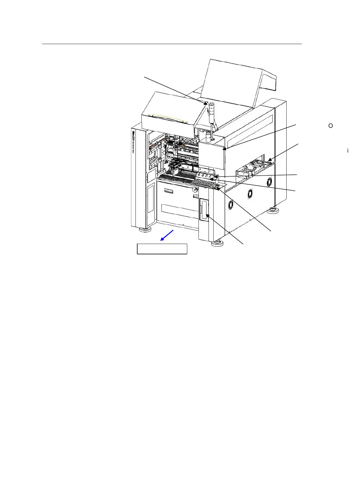
<Figure 4-1 Mx-Series SMD Mounter >
• TOWER LAMP: Indicates machine errors in three colors (red, yellow,
green).
• EMERGENCY SWITCH: Emergency stop switch used in an emergency
• 17” LCD Monitor: Used for vision & PC monitor
• OPERATING SWITCH: Ergonomic layout
• KEY BOARD & MOUSE: Improves operability
• COVER: Convenient structure and safety interlock
Structure The Mx-Series system consists of several assemblies as seen in <Figure 4-2>
below. Each
assembly is optimized by various tests. Users can configure a system
customized for components and production environment by replacing these
assemblies.
The assemblies are divided into five systems: Base Frame, PCB PCB
Transfer System, Component Feeding System, Positioning System and
Control System.
<Figure 4-3> shows the structure of Mx400 system.