Module Settings
30
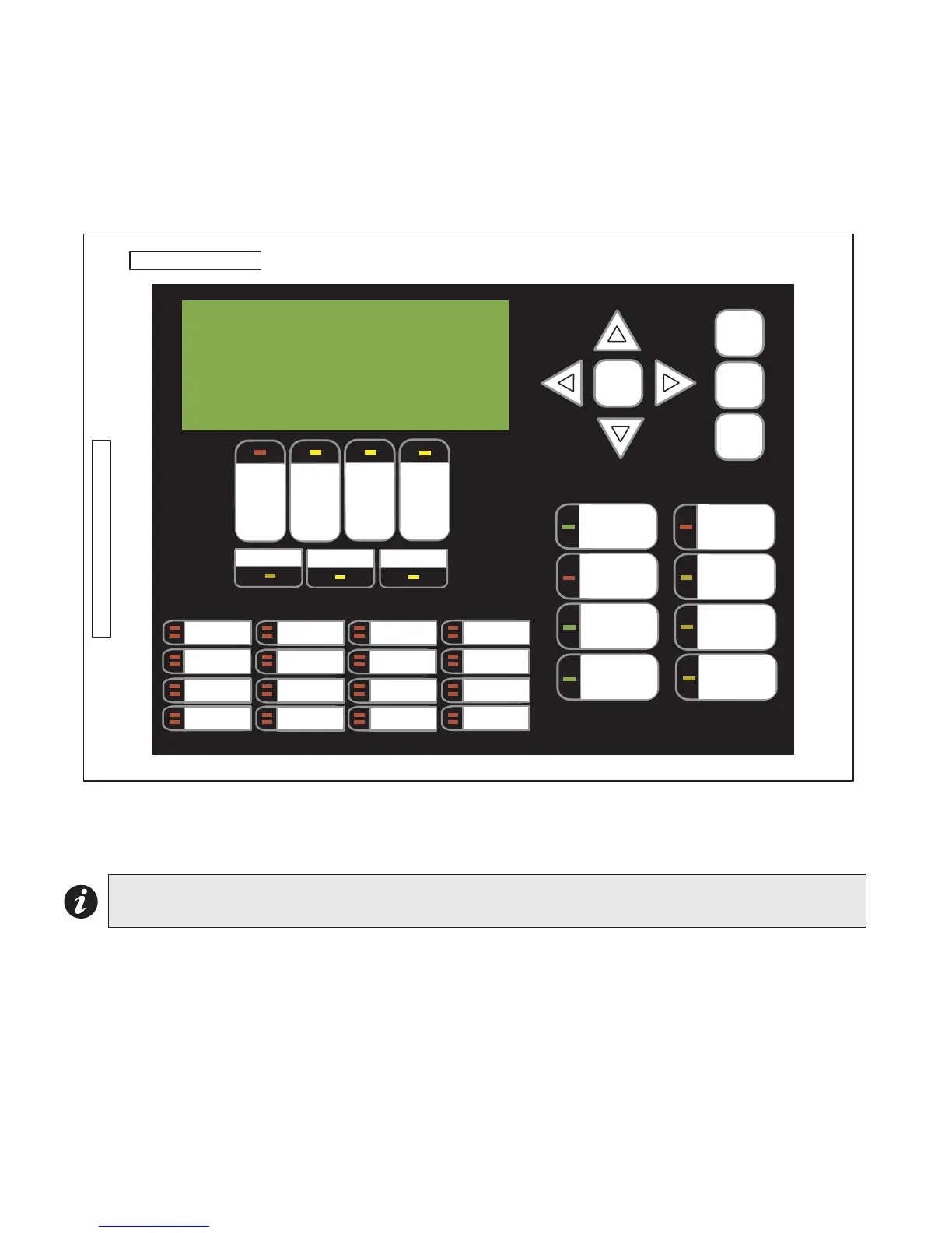
Main Display Module
The display module shown in Figure 14 is part of the following chassis: FX-2003-12N, FX-2009-12N, FX-2017-12N
and FX-2000ND.
Figure 14: Main Display Module (Part of Main Chassis)
P1: Cable connects to P14 of the FX-2000N main fire alarm board (Figure 11).
P2: Connection to P1 of any adder display module if used.
Note: The main display module comes with slide-in paper labels including both English and French slide-
ins, and laser printer-compatible blanks for zone labelling.
P1
P2
ALARM
QUEUE
SUPV.
QUEUE
TROUBLE
QUEUE
MONITOR
QUEUE
A.C. ON
CPU FAULT
GND FAULT
SIGNAL
SILENCE
GENERAL
ALARM
ACKNOW-
LEDGE
FIRE
DRILL
SYSTEM
RESET
LAMP
TEST
ENTER
MENU
CANCEL
INFO
LED 8
LED 9
LED 10
LED 11
LED 12
LED 13
LED 14
LED 15
LED 16
LED 17
LED 18
LED 19
LED 20
LED 21
LED 22
LED 23
CONFIGURABLE
SWITCH/LED 3
SWITCH/LED 1
SWITCH/LED 2
SWITCH/LED 4
SWITCH/LED 5
SWITCH/LED 6
SWITCH/LED 0
CONFIGURABLE
SWITCH/LED 7
MGC Network
Fire Control System
System Normal
March 7, 2013