Module Settings
32
Figure 16: FOM-2000-SP Fiber Optic Network Module
One of these modules is required at each panel where fiber optics will be used between them. The FOM-2000-SP
will be mounted over the FNC-2000 Network board (over the field wiring terminals) with two #6 Phillips screws and
two Hex spacers.
Table 2: FOM-2000-SP Fiber Optic Network Module Cable Connection
RAX-1048/TZ/TZDS Zone Display Module
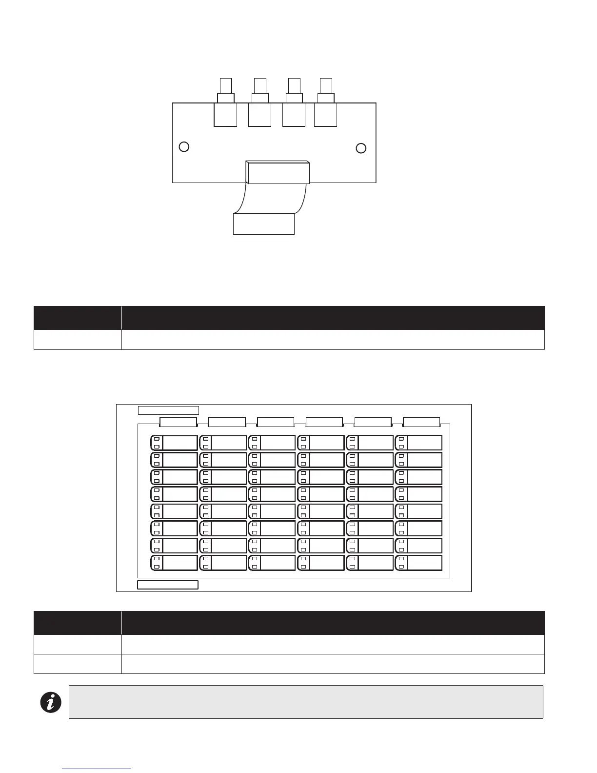
Figure 17: Zone Display Module (RAX-1048 or RAX-1048TZ/DS)
Table 3: RAX-1048/TZ/TZDS Zone Display Module Cable Function
Connector Function
P1 P1 cable attaches to P10 of the FNC-2000 Fire Network Controller Module.
Connector Function
P1 P1 Cable connects to P2 of previous display module.
P2 P2 Cable connects to P1 of next display module
Note: The zone display module comes with laser printer-compatible slide-in paper labels for zone labelling.
P1
RX2
RX1
TX2
TX1
P2
P1