24
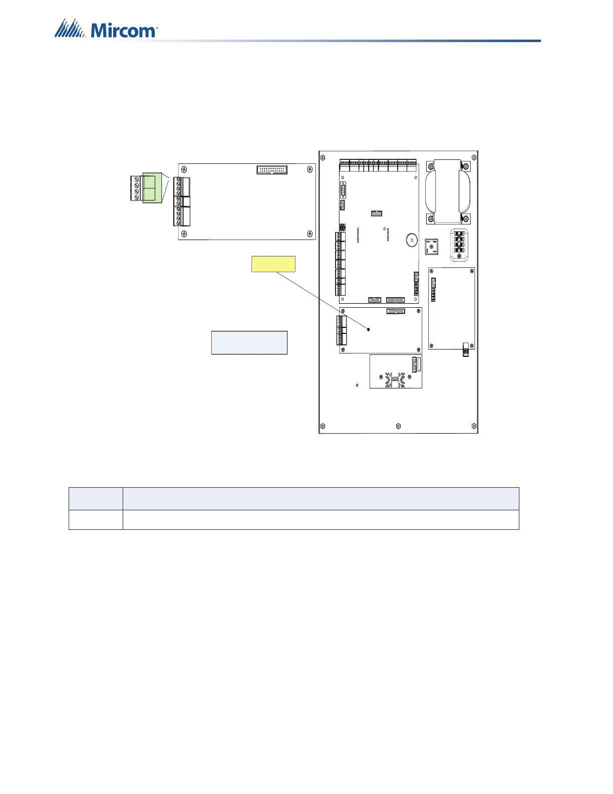
4.5 Installing the ALC-480 Dual Loop Adder
Mount the ALC-480 Dual Loop Adder as shown in Figure 7.
The ALC-480 provides two addressable loops (SLC). Each loop can accommodate 240 MIX-
4000 Series devices.
Figure 7 Installing the ALC-480 Dual Loop Adder
4.5.1 Installing the RAX-1048TZDS Display Adder Module
The FX-401 can have a maximum of two RAX-1048TZDS Display Adder Module. No jumpers
or other physical configuration steps are required to install the RAX-1048TZDS Display Adder
Modules.
To Install the RAX-1048TZDS Display Adder Module
1. Remove the blank cover plate from the front door and install the RAX-1048TZDS with
the clear cover in the opening with the hardware provided.
2. Disconnect main and standby power and connect the cable of the second RAX-
1048TZDS into the open, remaining header of the existing RAX-1048TZDS. The
additional LEDs will be available for configuration as LEDs 49 to 96, when the system
power is restored.
Table 6 ALC-480 Dual Loop Adder Connector
Item Setting
P1 Connect cable to P10 on the Main Board of the FX-401.
Mounted on hex spacer
with four screws provided
ALC-480
A LOOP1
B
+
-
+
-