64
7.4.3 UL 864 Rev. 10 Addressable Supervised Output Module Wiring
As per UL864 Rev.10 56.4.3, ensure that a single break, ground or wire-to-wire fault on the
installation conductors of a signalling circuit for use with addressable notification appliances or
modules shall not affect the operation of more than one notification zone.
Exception: Riser conductors installed in accordance with the survivability from attack by fire
requirements in National Fire Alarm Code, NFPA 72.
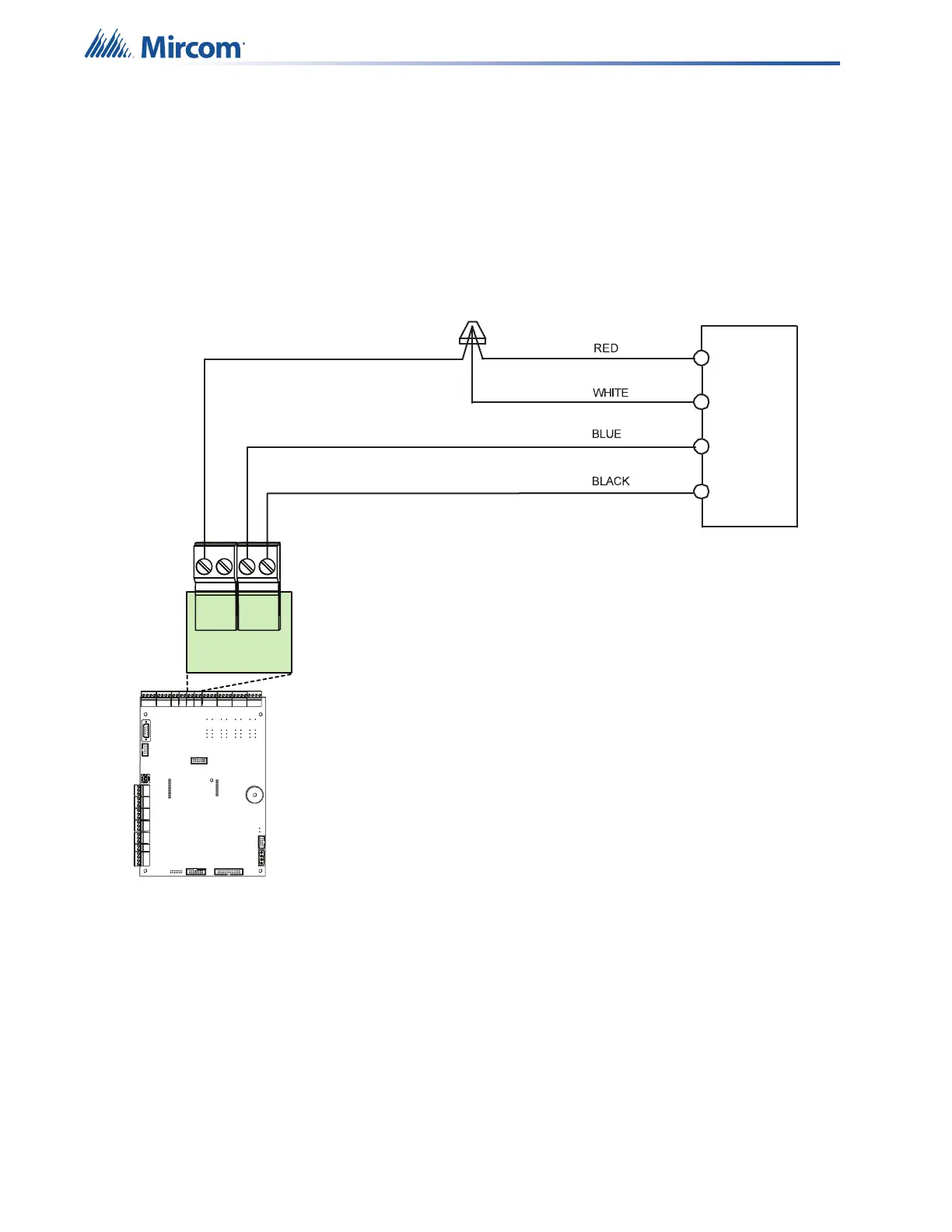
7.4.4 RTI-1 Common Remote Trouble Indicator Wiring
Figure 19 RTI-1 Common Remote Trouble Indicator Wiring
WIRE NUT
CONNECTION
RTI-1
Current: 35mA maximum
Voltage: 24V
Frequency: 20 pulses per minute (ppm)
Power Factor: 1
Use 20 AWG or larger
Maximum wiring distance of 4000 feet
RTI
+-
TRL TRB
UNFLTD
30