74
7.8 Placement of Ferrites for FCC Standard
7.8.1 Ferrite Locations
Two ferrites are required to be mounted on the wires coming from the loop terminals and the
auxiliary power terminals.
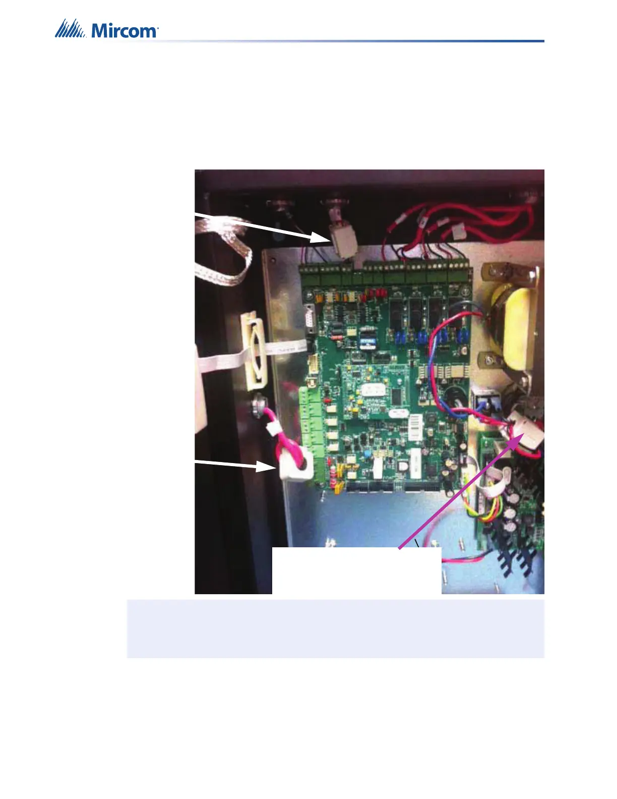
Refer to picture below, of the FX-401 main fire alarm board.
7.8.2 ALC-480 Dual Loop Adder Module
If an ALC-480 Dual Loop Adder Module is used with the FX-401, one ferrite is required for
each loop. The two ferrites are packed with the ALC-480. Place the wires coming out of Loop
1 through the ferrite and loop around the ferrite once and back out to connect to devices. If
using Loop 2, also place the wires coming out of Loop 2 through the second ferrite and loop
wires around the ferrite once and back out to connect to devices.
Note: Ferrites must be connected as stated for adherence of FCC Rules.
Ferrite labeled FER-003 is
used for Loop 1 wires as
shown here. The wires
coming out of the SLC
(Loop 1) on the main
board are fed through the
ferrite FER-003 and
looped around once and
out the ferrite as shown in
this photo.
Ferrite labeled FER-002 is
used to loop Aux 1 and Aux
2 wires if used. The wires
coming out of the Aux 1
and Aux 2 terminals (if
used) are fed through the
ferrite FER-002 and out
(NO LOOPING).
This ferrite (labeled FER-001) is
factory set. Do not tamper with or
remove.