59
7.1.3 NAC and Auxiliary Power Supply Circuits
7.1.4 Input Circuits
If using conventional detectors with an FX-401 FACP, MIX-4042 conventional zone modules
must be used. Refer to document LT-1023 for compatible devices.
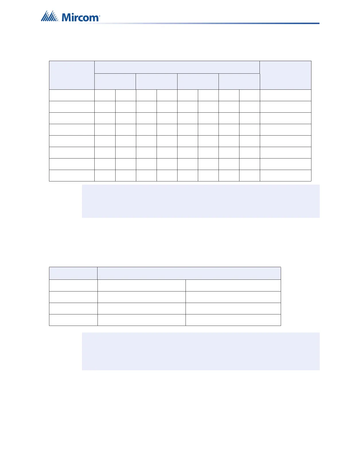
Table 15 NAC and Auxiliary Power Circuits Wiring Table
TOTAL
SIGNAL
LOAD
MAXIMUM WIRING RUN TO LAST DEVICE (ELR) MAX. LOOP
RESISTANCE
18AWG 16AWG 14AWG 12AWG
Amperes ft m ft m ft m ft m Ohms
0.06 2350 716 3750 1143 6000 1829 8500 2591 30
0.12 1180 360 1850 567 3000 915 4250 1296 15
0.30 470 143 750 229 1200 366 1900 579 6
0.60 235 71 375 114 600 183 850 259 3
0.90 156 47 250 76 400 122 570 174 2
1.20 118 36 185 56 300 91 425 129 1.5
1.50 94 29 150 46 240 73 343 105 1.2
Notes: Main Board NAC Circuits are rated for of 1.5 Amperes each.
Maximum Voltage Drop Should Not Exceed 1.67 Volts
Table 16 Conventional Zone Module Input Circuit Wiring Table
Wire Gauge Maximum Wiring Run to Last Device and Back (ELR)
(AWG) ft m
18 3787 1154
16 5952 1814
14 9615 2930
Notes: Maximum Loop Resistance Should Not Exceed 25 Ohms.
Maximum Wiring Run indicates wiring distance out and back to the panel. The
resistance across the shorted wire should be less than 25 Ohms.