58
7.0 Wiring
This chapter describes the proper field wiring for the FX-401.
7.1 Wiring Tables
7.1.1 Addressable Loop Wiring Maximums
MGC Devices
• Maximum Loop Current = 350 mA
• Maximum Loop Resistance = 40 ohms
• Maximum Loop Capacitance = 0.5 ȝF
• Inductance shall not exceed 1 mH
Shield for Analog Loop Wiring: Only twisted pair is recommended, but if shielded twisted
pair is used, wire shield at the start and the end of the loop to the terminals marked Shield at
the loop adder board.
7.1.2 RS-485 Wiring to Annunciators and other Devices
• Use twisted shielded pair
• 300mA power limited
• 22 AWG maximum of 2000 feet
• 20 AWG maximum of 4000 feet
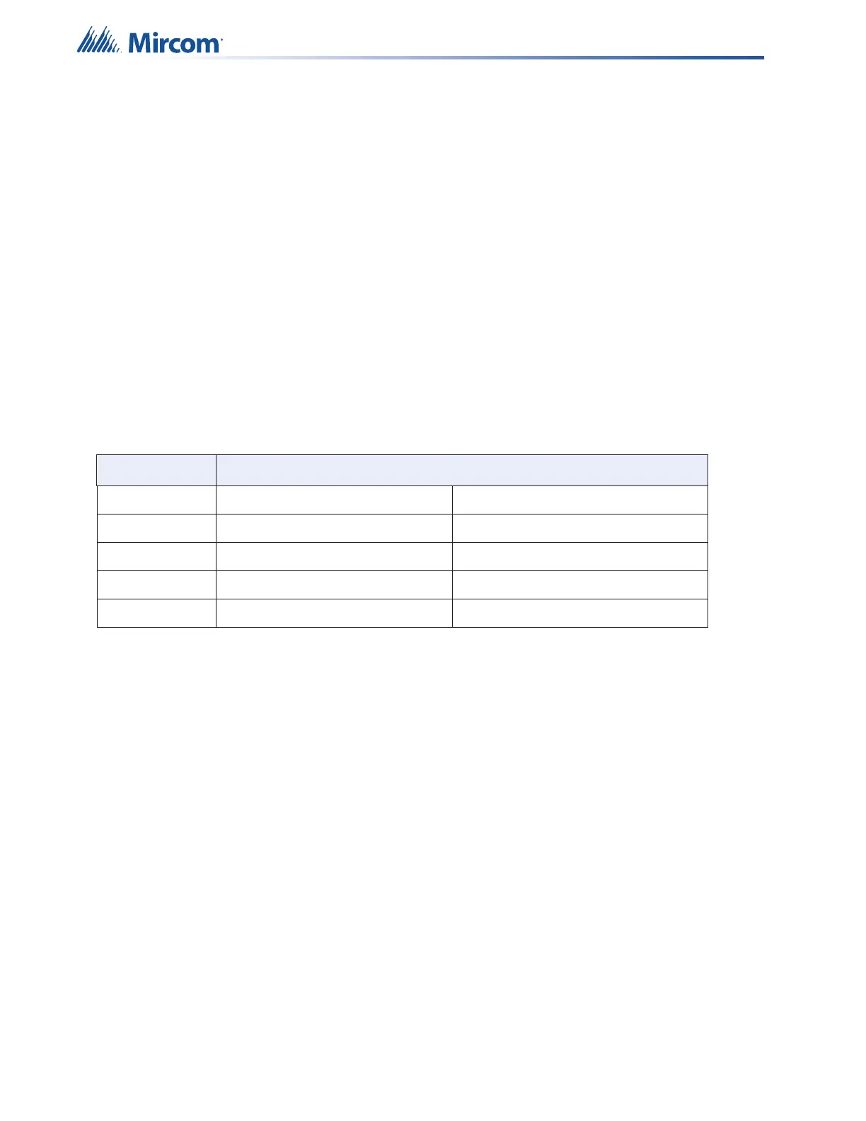
Table 14 MGC Devices Addressable Loop Wiring Table
Wire Gauge Maximum Wiring Run to Last Device
(AWG) ft m
12 10,000 3049
14 7971 2429
16 4980 1518
18 3132 955