85
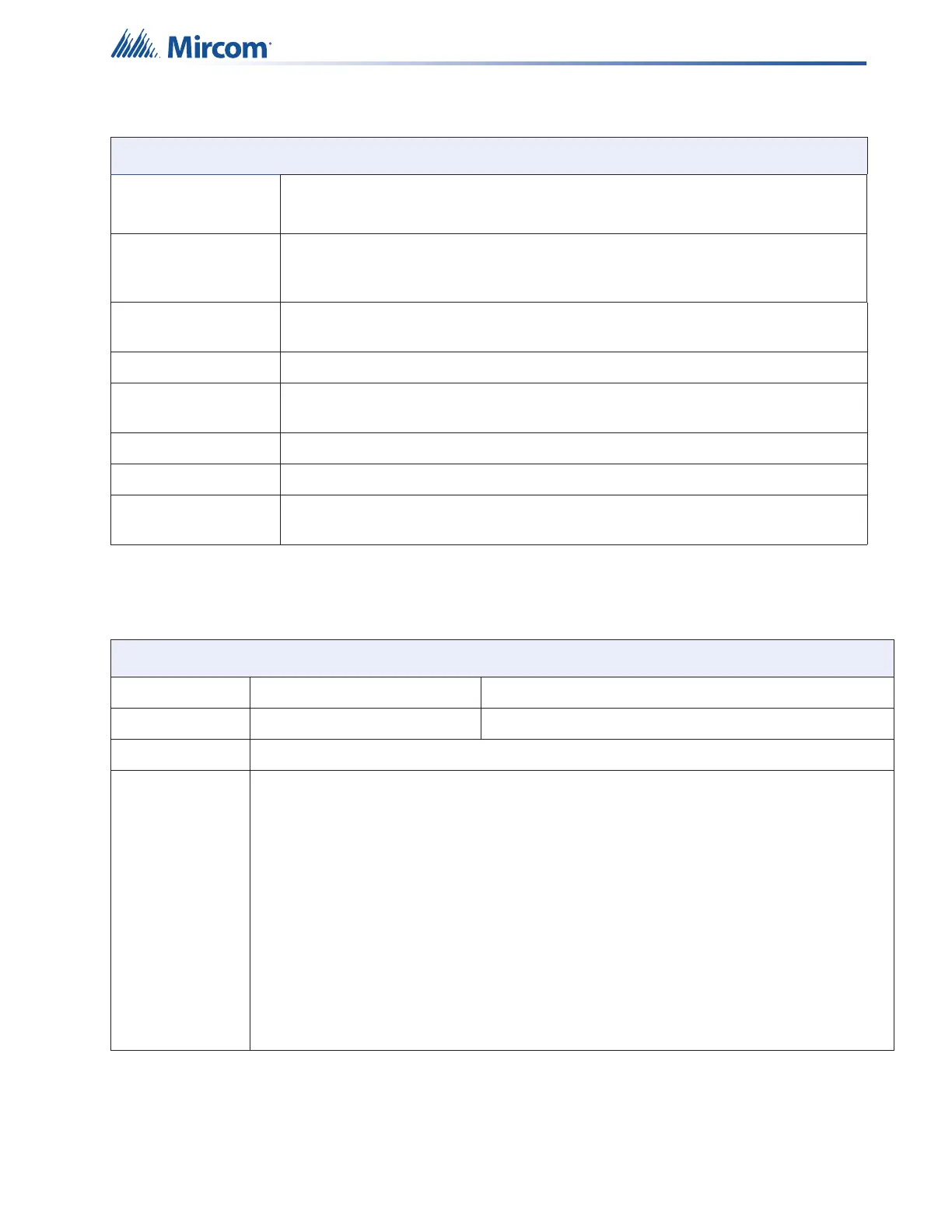
11.2 FX-401 System Module and Annunciator Specifications
Unfiltered supply Power limited / 24V FWR special application / 1.7A max at 49C
List of Compatible Devices: RAM-1032TZDS, RAM-3500-LCD, RAX-LCD-LITE
Auxiliary relays Common Alarm/
Supv./Trouble/
Auxiliary Alarm
Must be connected to a listed power limited source of
supply Form C/28VDC/1A max
TS1 Power Supply
Board
24VDC 1.4A Power Limited Special Application. 24.9 - 28.2 VDC recorded range
for compatibility. Supervised via EOLR-1A end-of-line relay.
RS-485 port For remote annunciators. Terminals are labelled “RS-485”
Ground Fault
Impedance
10 K Ohms
Open Circuit Fault 100 K Ohms
Short Circuit Fault 0 Ohms
Applicable
Standards
NFPA 70, 72, CAN/ULC-S559-13, UL-864 Rev. 10, ULC S524, CAN/ULC-S527-11
and ULC-S536-04
Table 22 FX-401 Modules and Annunciator Specifications
FX-401 System Modules and Annunciators
RAM-3500-LCD Remote Annunciator Standby 70mA / alarm 100mA
RAX-LCD-LITE Remote Annunciator Standby 65mA / alarm 80mA
RTI-1 Remote Trouble Indicator Normal standby 0mA / alarm 30mA maximum
PR-300 Polarity Reversal and City Tie Module
City Tie power limited / 24VDC unfiltered / 270mA max / 13.7 and
14.4 Ohms
Polarity Reversal power limited / 24VDC open / 12VDC at 3.5mA / 8mA
max (shorted)
Polarity Reversal Supv.
Terminal
24VDC (normal) / -24VDC (supervisory) / 0V (trouble)
Polarity Reversal Alarm
Terminal
24VDC (normal) / -24VDC (alarm) / 0V (trouble)
Current Consumption standby 50mA / alarm 300mA (city tie in use) / alarm
70mA (city tie not in use)
Table 21 FX-401 Specifications (Continued)
FX-401 Fire Alarm Control Panel