52
6.0 Indication & Controls
This chapter describes the LED indicators and controls of the FX-401.
6.1 Indication and Controls
FX-401 Display Panel is equipped with the following
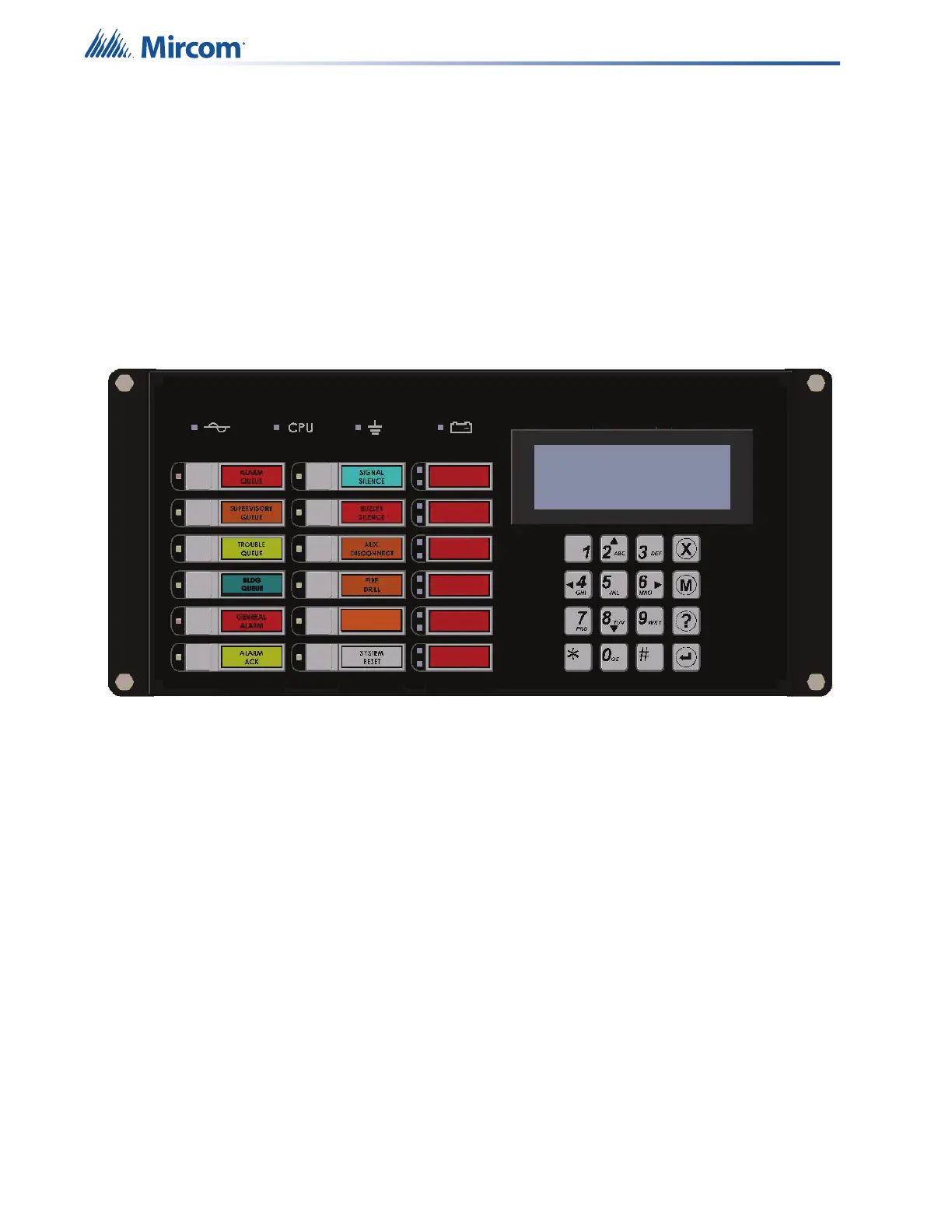
• 12 Control buttons with associated LEDs
• 16 button Numeric Keypad with Cursor buttons
Figure 11 displays the LED indicators and the control button on the FX-401 main board.
Figure 11 LED Indicators and Control Buttons
The FX-401 has the ability for 2 additional RAX-1048TZDS. Each RAX-1048TZDS Display
Adder Module provides annunciation for up to 48 Zones. Each LED zone has two LEDs.
• 1 Red/Yellow Alarm/Supervisory LED.
• 1 Yellow Trouble LED.
6.2 LCD Display
The display is a four line, 20 character back-lit alphanumeric LCD. It displays information
regarding the panel, its circuits, and devices. An on-screen cursor is controlled by the cursor
buttons for menu selection and control. Report information provided by the LCD display
includes:
• Alarm Log
• Event Log
• Current Levels
• Device Information
• Verification and Maintenance Reports
Use the cursor buttons on the Numeric Keypad for menu selection and control. For more
information see 6.2.1 Numeric Keypad and Cursor Buttons on page 53.
Visual
Indicator Test