Chapter 9
174
Logic programming – Function blocks
Parameters of the function block
Parameter Possible values
Number of incremental inputs 1 single encoder input
1 pair of encoder inputs
2 pairs of encoder inputs
Input plausibility checks Disabled
Enabled
If enabled, then the number of incremental inputs must be
either 1 pair or 2 pairs.
Min. time between signal
changes
100 ms to 10 s in steps of 10 ms. The value has to be
greater than the logic execution time.
Use fault present
With
Without
Ensure that your application fulfils the following requirements!
Encoder pulses must have a minimum duration of the logic execution time (see step
1 below).
Connect the signal that controls the physical output for the drive to the Drive
released input. It must be ensured that if this input is Low, the torque of the drive is
switched off in any case.
Encoders must be connected locally to a WS0-XTIO or WS0-XTDI module on the
same Flexi Link station (not via network or Flexi Link etc.)
Configuration steps
Check the minimum duration of the encoder pulses (see step 1 below).
Determine the time between signal changes for the speed limit (see step 2 below).
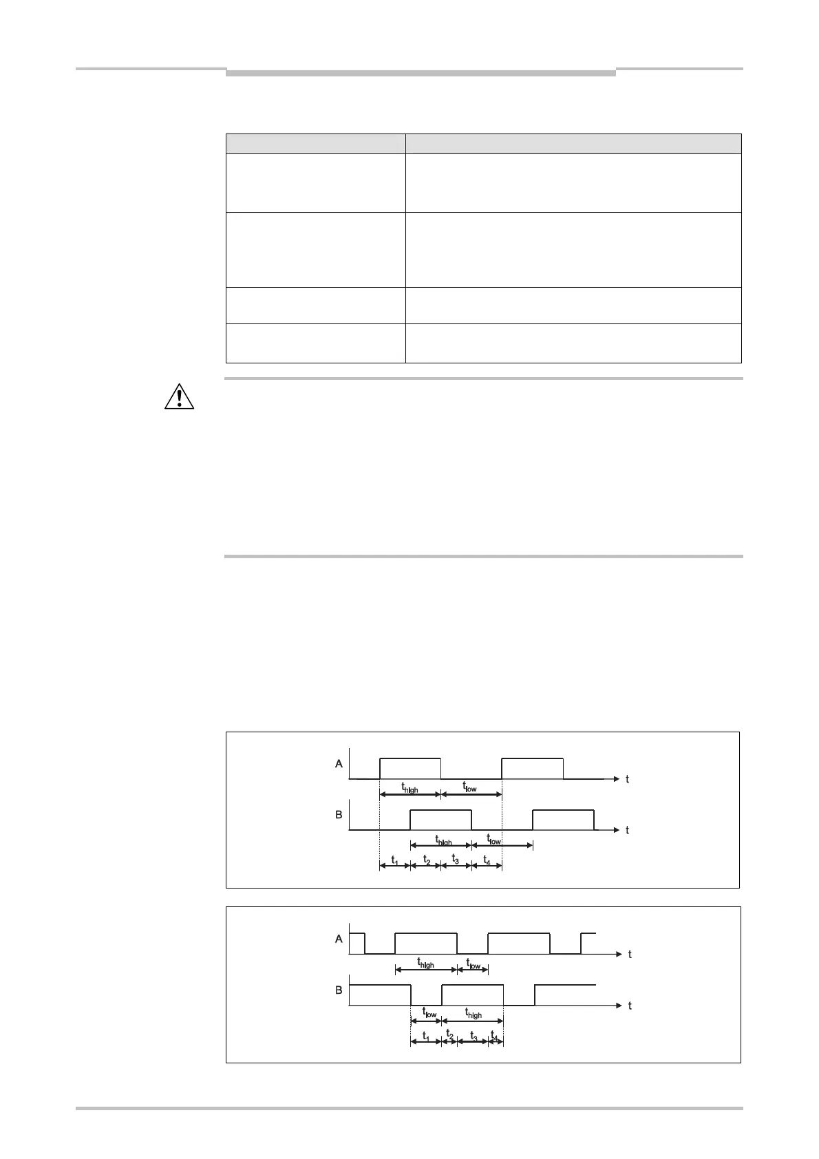
Step 1: Check the maximum signal frequency for incremental signals
The encoder pulses t
high
and t
low
must both have a minimum duration of the logic
execution time. This limits the allowed signal frequency and encoder speed depending
on the encoder type. The following figures show typical signal patterns for different
encoder types:
Table 76:
Parameters of the Ramp
down detection function
block
ATTENTION
Figure 159:
Signal pattern for A/B 90°
phase shift encoders
Figure 160:
Signal pattern for 1/3 gap
180° phase shift encoders

 Loading...


