Chapter 9
175
Logic programming – Function blocks
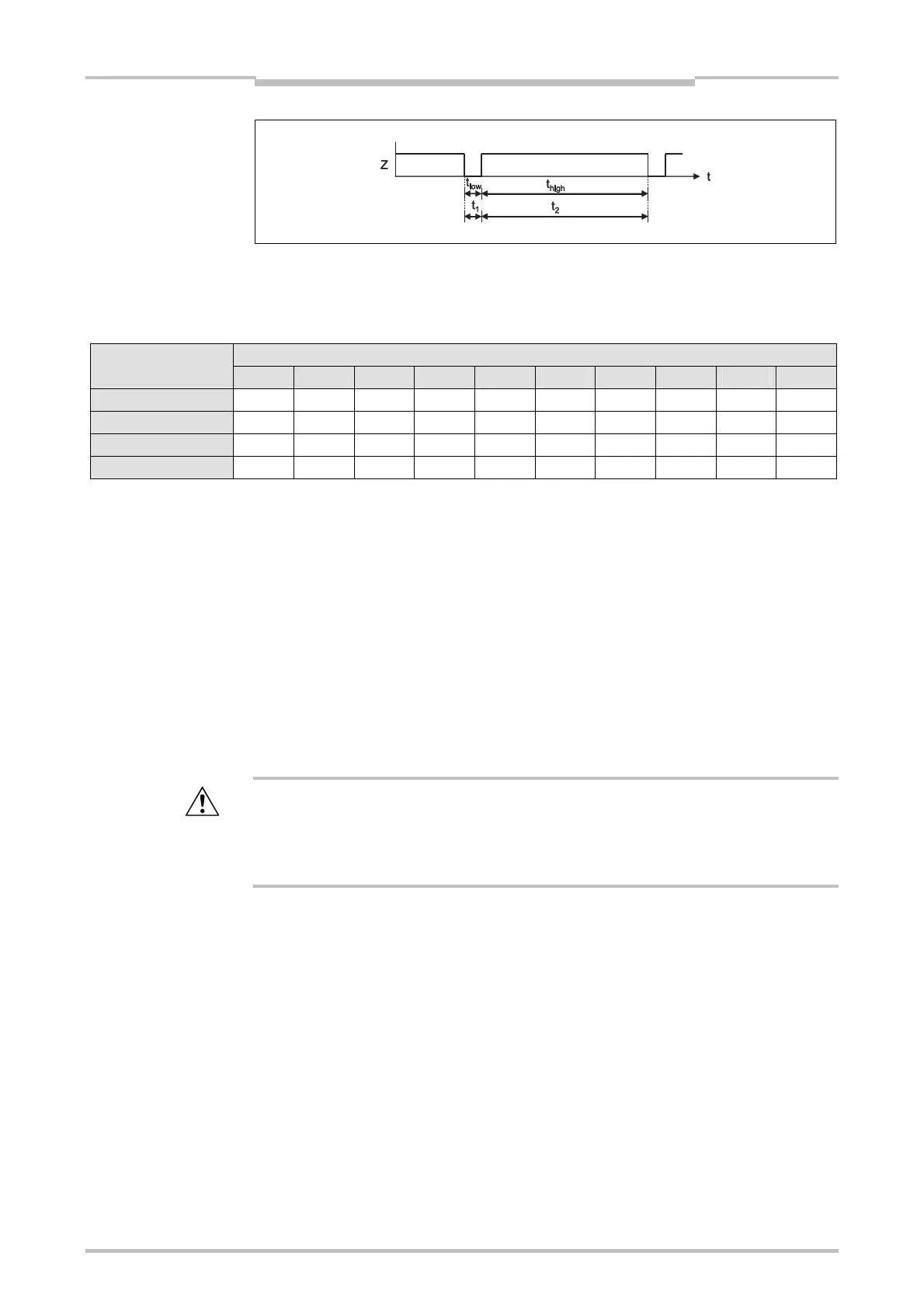
It must be ensured by the design of your system that the minimum duration of the
encoder pulses t
high
and t
low
must both be always higher than the logic execution time.
Take all possible tolerances into account, e.g. switching tolerances, tooth wheel
tolerances etc. The following table shows typical values for different encoder types.
Encoder type Max. allowed encoder signal frequency (Hz) for logic execution time
4 ms 8 ms 12 ms 16 ms 20 ms 24 ms 28 ms 32 ms 36 ms 40 ms
A/B, 90° phase shift 125.0 62.5 41.7 31.3 25.0 20.8 17.9 15.6 13.9 12.5
1/3 gap
*1
83.3 41.7 27.8 20.8 16.7 13.9 11.9 10.4 9.3 8.3
1/4 gap
*1
62.5 31.3 20.8 15.6 12.5 10.4 8.9 7.8 6.9 6.3
Pulse 180° 125.0 62.5 41.7 31.3 25.0 20.8 17.9 15.6 13.9 12.5
Table 77:
Maximum allowed encoder signal frequency and speed (rpm) depending on the encoder type and the logic
execution time
*1 180° phase shift, 1 signal min. always High.
Step 2: Determine the time between signal changes for the speed limit
Define the speed at which the Ramp down ended output shall be activated, e.g. to
unlock a safety door.
Define the maximum time that can pass between two signal changes at this speed
(highest values of t
1
to t
4
). Take all possible tolerances into account, e.g. switching
tolerances, tooth wheel tolerances etc.
Min. time between signal changes = highest values of t1 to t4 + 10 ms
In any case the Min. time between signal changes must be greater than the logic
execution time and must be rounded up to a multiple of 10 ms.
Take increased logic execution times into account!
Every time the logic program is changed, the logic execution time may increase. In
this case it may be necessary to check the maximum signal frequency for incremental
signals again. Otherwise the operator of the machine will be in danger.
Example 1: A/B 90° phase shift
4 teeth per revolution
Switching tolerances +/–5° teeth 175° to 185° (corresponds to t
low
, t
high
); signal
change 85° to 95° (corresponds to t
1
to t
4
)
Maximum shaft speed = 750 rpm = 12.5 Hz
Shaft speed for release = 15 rpm = 0.25 Hz
Logic execution time = 8 ms
Check the maximum signal frequency for incremental signals:
Max. signal frequency = 12.5 Hz × 4 teeth/revolution = 50 Hz
Smallest t
low
= 1/50 Hz × 175°/360° = 9.7 ms
greater than the logic execution time
Smallest t
high
= 1/50 Hz × 175°/360° = 9.7 ms
greater than the logic execution time
Figure 161:
Signal pattern for zero pulse
encoders
ATTENTION

 Loading...


