Chapter 7
89
Flexi Link
Configuring the logic for Station B
Click on the button for Station B in the toolbar. Then switch to the Logic editor view
for Station B.
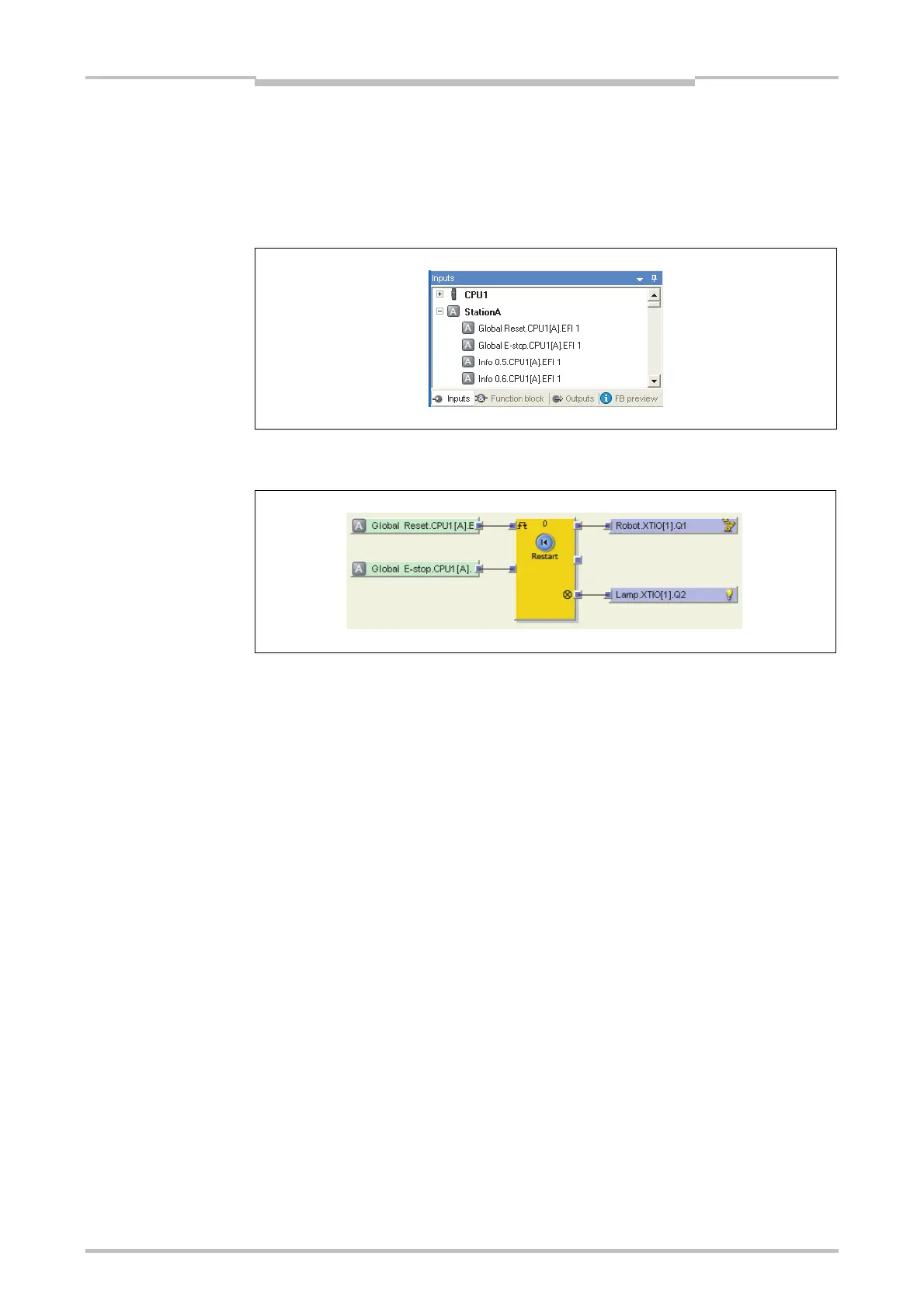
In the inputs selection window, find the two inputs from the Station A CPU module
that are routed via Flexi Link. You can recognize them by their tag names:
Using these inputs, the output elements on the Station B WS0-XTIO module and a
Restart function block, create the following logic configuration:
With this step the example project is finished. The input from the emergency stop
button and from the reset button connected to Station A is routed to Station B via Flexi
Link so that the robots connected to both stations can be controlled simultaneously.
Figure 60:
Routed inputs from Station
A in the Station B logic
editor
Figure 61:
Logic configuration example
(Station B)

 Loading...


