4G9 ENGINE (E-W) -
Piston and Connecting Rod
11A-11-4
PWEE9502
E
May 1995Mitsubishi Motors Corporation
"
B
A
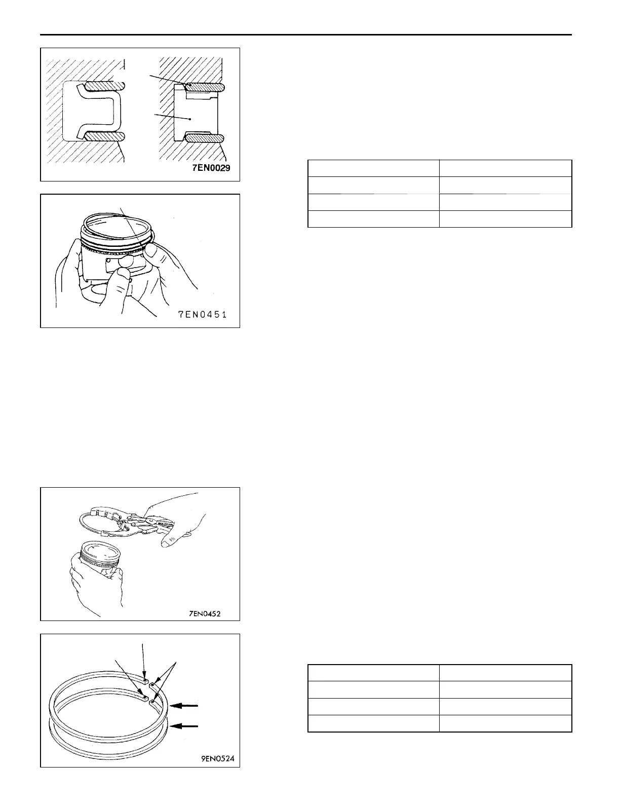
OIL RING INSTALLATION
(1) Fit the oil ring spacer into t he piston ring groove. Install
the upper side rail, and then install the lower side rail.
NOTE
1. The side rails and spacer may be installed in either
direction.
2. New spacer and side rail are painted with the following
identification colour according to the size.
Size Identification colour
Standard size None
0.50 mm O.S. Blue
1.00 mm O.S. Yellow
3. To install the side rail, first fit one end of the rail
into the piston groove, then press the remaining
portion into position by finger as shown in the
illustration.
Caution
Do not use piston ring expander when installing side
rail. Use of piston ring expander to expand the side
rail end gap can break the side rail, unlike other piston
rings.
(3) Make sure that the side rails move smoothly in either
direction.
"
C
A
PISTON RING NO.2/PISTON RING NO.1
INSTALLATION
(1) Using piston ring expander, install the piston rings with
their side having identification marks facing up.
Identification mark:
No.1 ring: T
No.2 ring: 2T
NOTE
The piston ring is stamped with t he following size mark.
Size Size mark
Standard size None
0.50 mm O.S. 50
1.00 mm O.S. 100
Side rail
Spacer
Side rail end
Identification mark “T”
Identification mark “2T”
Size mark
No.1
No.2
 Loading...