4G9 ENGINE (E-W) -
Piston and Connecting Rod
11A-11-6
PWEE9502
E
May 1995Mitsubishi Motors Corporation
"
F
A
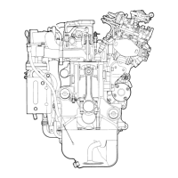
CONNECTING ROD CAP INSTALLATION
(1) Mate the correct bearing cap with the correct connecting
rod by checking with the alignment marks marked during
disassembly. If a new connecting rod has no alignment
mark, position the notches for locking the bearing on
the same side.
(2) Check if the thrust clearance in the connecting rod big
end is correct.
Standard value: 0.10 - 0.25 mm
Limit: 0.4 mm
"
G
A
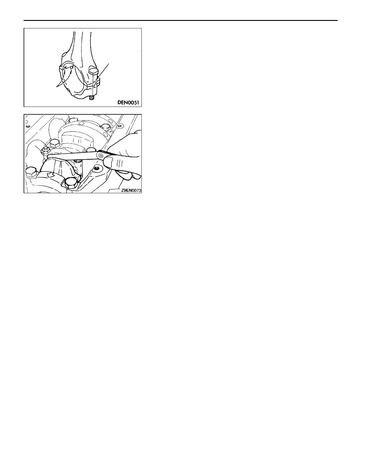
CONNECTING ROD CAP NUT INSTALLATION
Caution
If the cylinder head has been installed before installing
the connecting rod cap nut, be sure to remove the spark
plugs.
(1) Since the connecting rod cap bolts and nuts are torqued
using the plastic area tightening method, the bolts should
be examined BEFORE reuse. If t he bolt threads are
“necked down”, the bolt should be replaced.
Necking can be checked by running a nut with fingers
to the full length of the bolt threads. If the nut does not
run down smoothly, the bolt should be replaced.
(2) Before installation of each nut, apply engine oil to the
thread portion and bearing surface of the nut.
(3) Install each nut to the bolt and tighten it with fingers.
Then tighten the nuts alternately to install the cap properly.
(4) Tighten the nuts to a torque of 20 Nm.
Cylinder No.
Notches
 Loading...