4G9 ENGINE (E-W)
-
Crankshaft, Cylinder Block, Flywheel and Drive Plate
11A-12-5
PWEE9502-A
E
Nov. 1995Mitsubishi Motors Corporation Revised
"
F
A
DRIVE PLATE BOLT/FLYWHEEL BOLT
INSTALLATION
(1) Remove all the ramaining sealant from bolts and thread
holes of crankshaft.
(2) Apply engine oil to the flange of bolt.
(3) Apply engine oil into the thread holes of crankshaft.
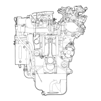
(4) Apply specified sealant to the thread of bolts.
Specified sealant:
3M Nut Locking Part No. 4171 or equivalent
(5) Tighten the bolts to specified torque.
INSPECTION
CRANKSHAFT JOURNAL OIL CLEARANCE
(PLASTIGAUGE METHOD)
(1) Remove oil from the crankshaft journal and he crankshaft
bearing.
(2) Install th e crankshaft.
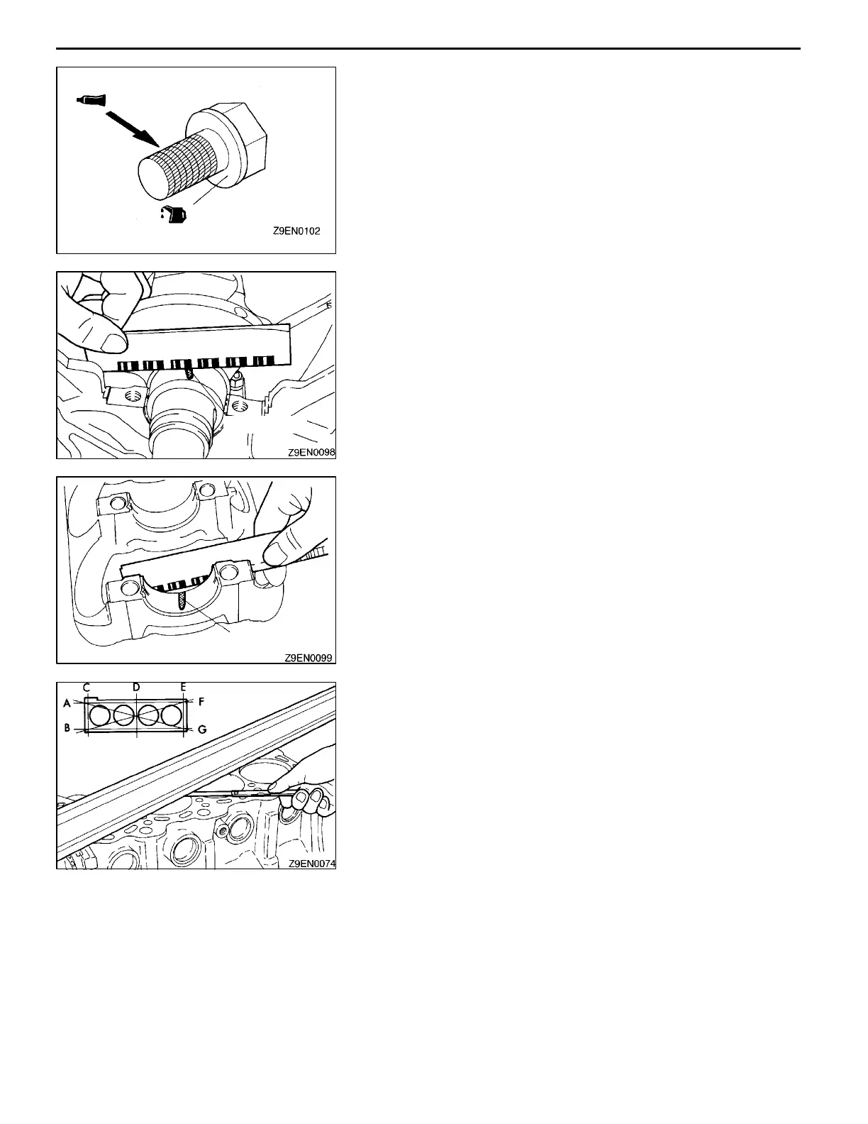
(3) Cut the Plastigauge to the same length as the width of
bearing and place it on the journal in parallel with its
axis.
(4) Install the crankshaft bearing cap carefully and tighten
the bolts to the specified torque.
(5) Carefully remove the crankshaft bearing cap.
(6) Measure the width of t h e Plastigauge at its widest part
by using a scale printed on the Plastigauge package.
Standard value: 0.02 - 0.04 mm
Limit: 0.1 mm
CYLINDER BLOCK
(1) Using a straightedge and thickness gauge, check the
block top surface for warpage. Make sure that the surface
is free from gasket chips and other foreign matter.
Standard value: 0.05 mm or less
Limit: 0.1 mm
(2) If the distortion is excessive, correct within the allowable
limit or replace.
Grinding limit: 0.2 mm
The total thickness of the stock allowed to be
removed from cylinder block and mating cylinder
head 0.2 mm at maximum.
Cylinder block height (when new):
243.5 mm <4G92>
263.5 mm <4G93>
(3) Check the cylinder walls for scratches a nd seizure. If
defects are evident, correct (bored to oversize) or replace.
Plastigauge
Plastigauge
 Loading...