431
FX3G/FX3U/FX3GC/FX3UC Series
Programming Manual - Basic & Applied Instruction Edition
15 External FX I/O Device – FNC 70 to FNC 79
15.5 FNC 74 – SEGL / Seven Segment With Latch
11
FNC30-FNC39
Rotation and
Shift
12
FNC40-FNC49
Data Operation
13
FNC50-FNC59
High-Speed
Processing
14
FMC60-FNC69
Handy
Instruction
15
FNC70-FNC79
External FX I/O
Device
16
FNC80-FNC89
External FX
Device
17
FNC100-FNC109
Data
Transfer 2
18
FNC110-FNC139
Floating Point
19
FNC140-FNC149
Data
Operation 2
20
FNC150-FNC159
Positioning
Control
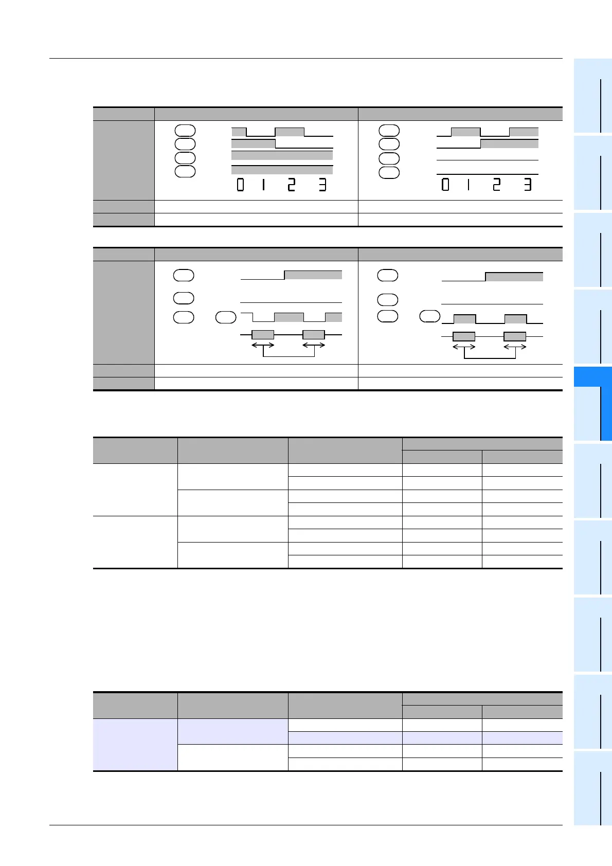
3. Confirming the logic of the seven-segment display unit
1) Data input
2) Strobe signal
4. Setting the parameter "n"
Set a proper value according to the logic (positive or negative) of the PLC and the logic (positive or negative) of the
seven-segment display unit as shown in the table below:
5. Explanation of the parameter "n" setting method according to an actual example
When the following seven-segment display unit is selected, "n" should be "1" when one display unit is connected (4
digits × 1 set) or "5" when two display units are connected (4 digits × 2 sets).
1) Transistor output of PLC
- Sink output = Negative logic
- Source output = Positive logic
2) Seven-segment display unit
- Data input = Negative logic
- Strobe signal = Positive logic
Logic Negative logic Positive logic
Timing chart
Description BCD data at low level BCD data at high level
Check
Logic Negative logic Positive logic
Timing chart
Description Data latched at low level is held. Data latched at high level is held.
Check
PLC output logic Data input Strobe signal
Parameter "n"
4 digits × 1 set 4 digits × 2 sets
Negative logic
Negative logic (match)
Negative logic (match) 0 4
Positive logic (mismatch) 1 5
Positive logic (mismatch)
Negative logic (match) 2 6
Positive logic (mismatch) 3 7
Positive logic
Positive logic (match)
Positive logic (match) 0 4
Negative logic (mismatch) 1 5
Negative logic (mismatch)
Positive logic (match) 2 6
Negative logic (mismatch) 3 7
PLC output logic Data input Strobe signal
Parameter "n"
4 digits × 1 set 4 digits × 2 sets
Negative logic
Negative logic (match)
Negative logic (match) 0 4
Positive logic (mismatch) 1 5
Positive logic (mismatch)
Negative logic (match) 2 6
Positive logic (mismatch) 3 7
Seven-segment
display
2
1
4
8
H
H
HH
H
L
L
L
+1
+2
+3
D
D
D
D
+1
Seven-segment
display
2
1
4
8
HH
H
+2
+3
D
D
D
D
H
Change in
strobe display
1
8
Latch
Nothing Nothing
HLHL
...
+4 to +7
+3
...
D
D
D
D
H
H
...
H
Change in
strobe display
1
8
Latch
Nothing Nothing
+4 to +7
+3
...
D
D
D
D

 Loading...


