549
FX3G/FX3U/FX3GC/FX3UC Series
Programming Manual - Basic & Applied Instruction Edition
20 Positioning Control – FNC150 to FNC159
20.6 FNC157 – PLSV / Variable Speed Pulse Output
11
FNC30-FNC39
Rotation and
Shift
12
FNC40-FNC49
Data Operation
13
FNC50-FNC59
High-Speed
Processing
14
FMC60-FNC69
Handy
Instruction
15
FNC70-FNC79
External FX I/O
Device
16
FNC80-FNC89
External FX
Device
17
FNC100-FNC109
Data
Transfer 2
18
FNC110-FNC139
Floating Point
19
FNC140-FNC149
Data
Operation 2
20
FNC150-FNC159
Positioning
Control
20.6 FNC157 – PLSV / Variable Speed Pulse Output
Outline
This instruction outputs variable speed pulses with an assigned rotation direction.
→ For explanation of the instruction, refer to the Positioning Control Edition manual.
→ For cautions on using special high-speed output adapters,
refer to the Positioning Control Edition manual.
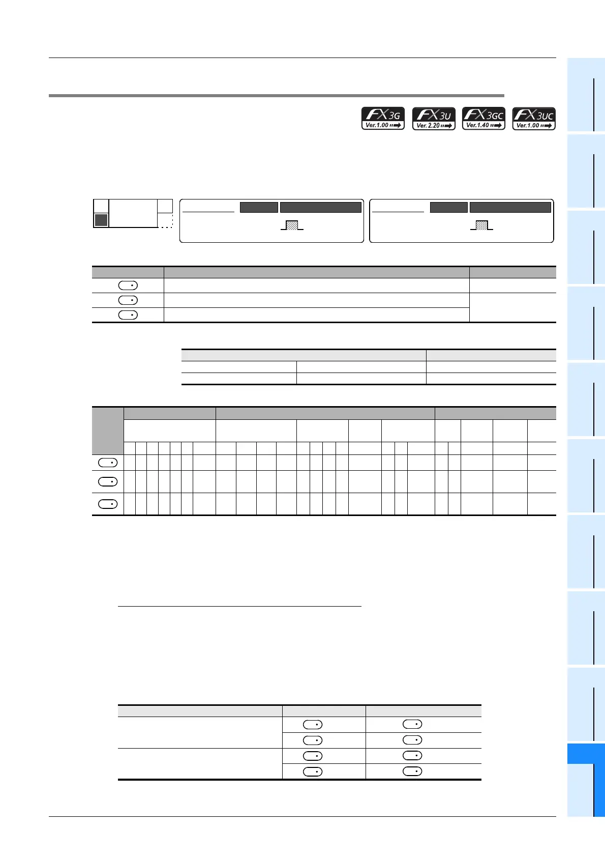
1. Instruction format
2. Set data
*1. Setting range: −32768 to −1, +1 to +32767 (except 0) Hz for 16-bit operation
Following range for 32-bit operation
3. Applicable devices
S1 : Specify Y000, Y001 or Y002
*1
transistor output from the main unit, or specify Y000, Y001, Y002
*3
or Y003
*3
from a high-speed output special adapter
*2
.
*1. Y002 is not available in FX3G PLC (14-point and 24-point type) and FX3GC PLC.
*2. High-speed output special adapters can be connected only to FX3U PLC.
*3. To use Y002 or Y003 with a high-speed output special adapter, connected a second high-speed output
special adapter.
Points
• When using a relay output type or triac output type FX3U PLC, a special high-speed output adapter is
required.
• Outputs of special high-speed output adapters work as differential line drivers.
S2 : When using a special high-speed output adapter for the pulse output destination in an FX3U PLC, the rotation
direction signal must be used by the following table output.
When using a built-in transistor output for the pulse output destination in an FX3G/FX3U/FX3GC/FX3UC PLCs, the
rotation direction signal must use transistor output.
S3:"D.b" is available only in FX
3U and FX3UC PLCs. However, index modifiers (V and Z) are not available.
S4 : This function is supported only in FX3U/FX3UC PLCs.
Operand type Description Data type
Device number for output pulse frequency
*1
16- or 32-bit binary
Device number (Y) from which pulses are to be output
Bit
Device number to which rotation direction signal is output
Pulse output destination Setting range
FX3U PLC Special high-speed output adapter −200,000 to −1, +1 to 200,000 (Hz)
FX3G/FX3U/FX3GC/FX3UC PLCs Main unit (transistor output) −100,000 to −1, +1 to 100,000 (Hz)
Oper-
and
Type
Bit Devices Word Devices Others
System User Digit Specification System User
Special
Unit
Index
Con-
stant
Real
Number
Charac-
ter String
Pointer
XYMTCSD.b KnX KnY KnM KnS T C D R U\G VZModifyKH E ""P
33333333S4 33 3 33
S
1
3
S
2
33S3 3
Special high-speed output adapter No. Pulse output Rotation direction output
No. 1 (1st unit)
=Y000
=Y004
=Y001
=Y005
No. 2 (2nd unit)
=Y002
=Y006
=Y003
=Y007
FNC 157
PLSV
D
PLSV
16-bit Instruction
7 steps
Mnemonic Operation Condition
Continuous
Operation
DPLSV
32-bit Instruction
13 steps
Mnemonic Operation Condition
Continuous
Operation
S
1
D
1
D
2
S
1
D
1
D
2
D
1
D
2
D
1
D
2
D
1
D
2
D
1
D
2

 Loading...


