438
FX3G/FX3U/FX3GC/FX3UC Series
Programming Manual - Basic & Applied Instruction Edition
15 External FX I/O Device – FNC 70 to FNC 79
15.8 FNC 77 – PR / Print (ASCII Code)
15.8 FNC 77 – PR / Print (ASCII Code)
Outline
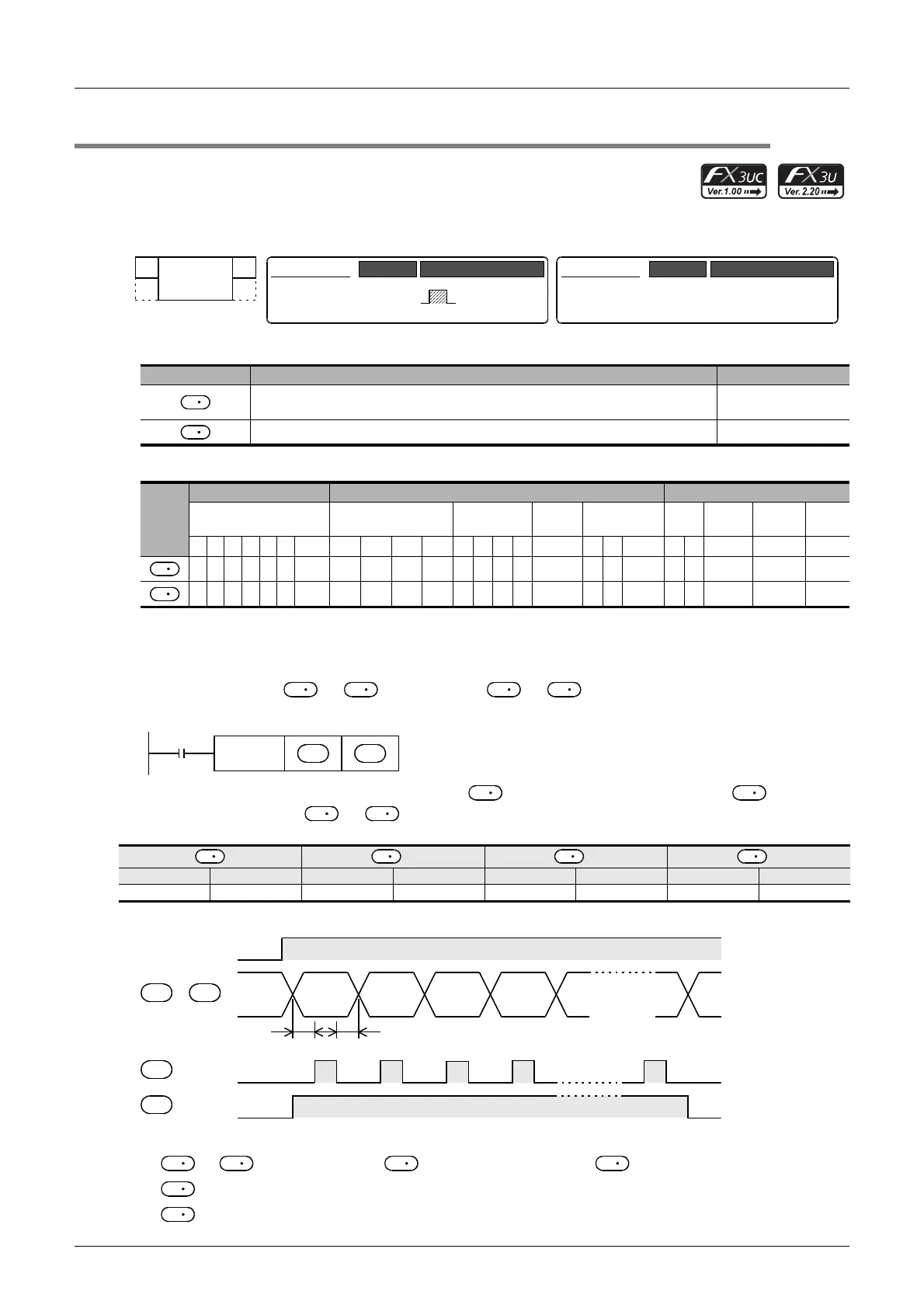
This instruction outputs ASCII code data to outputs (Y) in parallel.
1. Instruction format
2. Set data
3. Applicable devices
Explanation of function and operation
1. 16-bit operation (PR)
ASCII codes stored of to +3 are output to to +7 in turn by one character at a time in the
time division method.
Eight bytes are sent from the low-order 8 bits (1 byte) of first to the high-order 8 bits (1 byte) of +3 at the end.
When data is stored from to +3 as shown in the table below, data is sent in the order of A to H of "2.
Timing chart".
2. Timing chart
Types of output signals
• to +7: Sending output ( handles low-order bits, and +7 handles high-order bits.)
• +8: Strobe signal
• +9: Execution flag which operates as shown in the above timing chart
Operand Type Description Data Type
Head device number storing ASCII code data
Character string
(only ASCII codes)
Head output (Y) number to which ASCII code data is output Bit
Oper-
and
Type
Bit Devices Word Devices Others
System User Digit Specification System User
Special
Unit
Index
Con-
stant
Real
Number
Charac-
ter String
Pointer
XYMTCSD
.b KnX KnY KnM KnS T C D R
U\G
V Z Modify K H E "
"P
3333 3
3 3
+1 +2 +3
high-order 8 bits low-order 8 bits high-order 8 bits low-order 8 bits high-order 8 bits low-order 8 bits high-order 8 bits low-order 8 bits
B (H42) A (H41) D (H44) C (H43) F (H46) E (H45) H (H48) G (H47)
FNC 77
PR
−
32-bit Instruction
Mnemonic Operation Condition
PR
16-bit Instruction
5 steps
Mnemonic Operation Condition
Continuous
Operation
S
D
S
D
S
S
D
D
Command
input
FNC 77
PR
S
D
S
S
S
S
S
S S S
T
0
T
0
T
0
T
0
: Scan time (ms)
ABCD H
Command input
to +7 Data
+8 Strobe
+9 Execution flag
D D
D
D
D
D
D
D
D
D
 Loading...


