447
FX3G/FX3U/FX3GC/FX3UC Series
Programming Manual - Basic & Applied Instruction Edition
15 External FX I/O Device – FNC 70 to FNC 79
15.10 FNC 79 – TO / Write To A Special Function Block
11
FNC30-FNC39
Rotation and
Shift
12
FNC40-FNC49
Data Operation
13
FNC50-FNC59
High-Speed
Processing
14
FMC60-FNC69
Handy
Instruction
15
FNC70-FNC79
External FX I/O
Device
16
FNC80-FNC89
External FX
Device
17
FNC100-FNC109
Data
Transfer 2
18
FNC110-FNC139
Floating Point
19
FNC140-FNC149
Data
Operation 2
20
FNC150-FNC159
Positioning
Control
2. 32-bit operation (DTO and DTOP)
PLC (word device) → Special extension unit/block (BFM)
"n"-point 32-bit data starting from [ , +1] inside a PLC are transferred (written) to "n"-point buffer memories
starting from the buffer memory (BFM) # [m2+1, m2] inside a special extension unit/block No. m1.
Related devices
Cautions
• Digit specification in bit device
For the 16-bit operation instruction, specify K1 to K4. For the 32-bit operation instruction, specify K1 to K8.
• Note that the 32-bit values [m1+1, 1], [m2+1, m2] and [n+1, n] are valid when D or R is specified as "m1", "m2" or
"n" in a 32-bit instruction.
In the case of "DTO D0 D2 D100 R0", "m1" is [D1, D0], "m2" is [D3, D2], and "n" is [R1, R0].
Program examples
In programs, the contents of data registers (D), extension registers (R), auxiliary relays (M) with digit specification and
constants (K and H) are written (transferred) to buffer memories (BFMs) in special extension units/blocks using the TO
instruction and direct specification of buffer memories
*1
.
*1. This function is supported only in FX3U/FX3UC PLCs.
Example: When writing "H0" to the BFM #27 (command) in the CC-Link/LT master unit (whose unit number is fixed to
"0") built in the FX
3UC-32MT-LT(-2)
-In case of TO instruction
-In case of MOV instruction
Device Name Description
M8028 Enable interrupt flag
Disables or enables interrupts while FROM/TO instruction is executed.
→ For details, refer to "Acceptance of interrupt while FROM/TO instruction is executed
(M8028)" in Subsection 15.9.1.
OFF: Disables interrupts.
(Interrupts are executed after FROM/TO instruction is executed.)
ON: Enables interrupts.
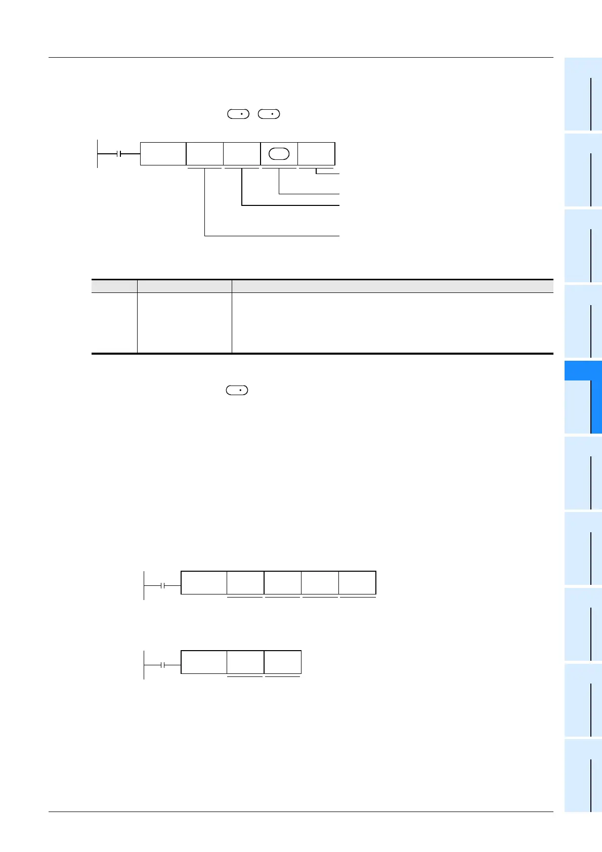
S
S
Command
input
FNC 79
DTO
m1 m2 n
Unit No.
m1 = 0 to 7
Transfer destination (Special
extension unit/block) BFM #
m2 = 0 to 32765
Transfer source (PLC)
Number of transfer points
n = 1 to 16383
S
S
M1
Unit
No. 0
BFM #27 Transfer
source
data
Number of
Transfer
points
FNC 79
TOP
K0 K27 H0 K1
M1
Transfer
source
data
Unit No. 0
BFM #27
FNC 12
MOVP
H0 U0\G27

 Loading...


