471
FX3G/FX3U/FX3GC/FX3UC Series
Programming Manual - Basic & Applied Instruction Edition
16 External FX Device – FNC 80 to FNC 89
16.9 FNC 88 – PID / PID Control Loop
11
FNC30-FNC39
Rotation and
Shift
12
FNC40-FNC49
Data Operation
13
FNC50-FNC59
High-Speed
Processing
14
FMC60-FNC69
Handy
Instruction
15
FNC70-FNC79
External FX I/O
Device
16
FNC80-FNC89
External FX
Device
17
FNC100-FNC109
Data
Transfer 2
18
FNC110-FNC139
Floating Point
19
FNC140-FNC149
Data
Operation 2
20
FNC150-FNC159
Positioning
Control
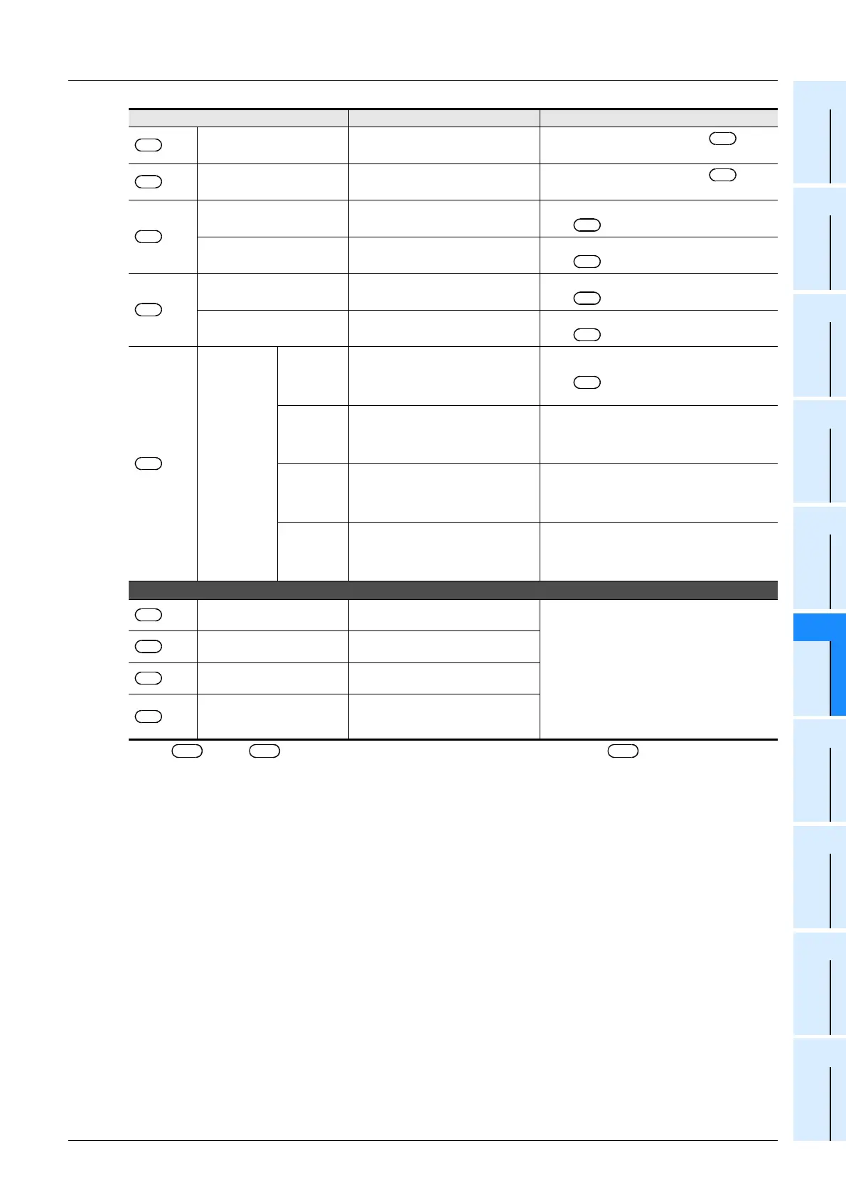
*1. +20 to +24 are occupied when any bit 1, 2 or 5 is set to "1" in +1 for operation setting
(ACT).
+20
*1
Input variation (incremental)
alarm set value
0 to 32767
It is valid when bit 1 is set to "1" in +1 for
the operation setting (ACT).
+21
*1
Input variation (decremental)
alarm set value
0 to 32767
It is valid when bit 1 is set to "1" in +1 for
the operation setting (ACT).
+22
*1
Output variation (incremental)
alarm set value
0 to 32767
It is valid when bit 2 is set to "1" and bit 5 is set to
"0" in +1 for the operation setting (ACT).
Output upper limit set value −32768 to 32767
It is valid when bit 2 is set to "0" and bit 5 is set to
"1" in +1 for the operation setting (ACT).
+23
*1
Output variation (decremental)
alarm set value
0 to 32767
It is valid when bit 2 is set to "1" and bit 5 is set to
"0" in +1 for the operation setting (ACT).
Output lower limit set value −32768 to 32767
It is valid when bit 2 is set to "0" and bit 5 is set to
"1" in +1 for the operation setting (ACT).
+24
*1
Alarm output
bit0
0: Input variation (incremental) is not
exceeded.
1: Input variation (incremental) is
exceeded.
It is valid when bit 1 is set to "1" or bit 2 is set to
"1" in +1 for the operation setting (ACT).
bit1
0: Input variation (decremental) is not
exceeded.
1: Input variation (decremental) is
exceeded.
bit2
0: Output variation (incremental) is not
exceeded.
1: Output variation (incremental) is
exceeded.
bit3
0: Output variation (decremental) is
not exceeded.
1: Output variation (decremental) is
exceeded.
The setting below is required when the limit cycle method is used (when bit 6 is set to "ON" in the operation setting (ACT)).
+25
PV value threshold
(hysteresis) width (SHPV)
Set it according to the fluctuation of the
measured value (PV).
They are occupied when bit 6 is set to "ON (limit
cycle method)" in the operation setting (ACT).
+26
Output value upper limit (ULV)
Set the maximum value (ULV) of the
output value (MV).
+27
Output value lower limit (LLV)
Set the minimum value (LLV) of the
output value (MV).
+28
Wait setting from end of tuning
cycle to start of PID control
(Kw)
−50 to 32717%
Set item Setting Value Remarks
S
3
S
3
S
3
S
3
S
3
S
3
S
3
S
3
S
3
S
3
S
3
S
3
S
3
S
3
S
3
S
3
S
3
S
3
S
3

 Loading...


