659
FX3G/FX3U/FX3GC/FX3UC Series
Programming Manual - Basic & Applied Instruction Edition
29 Data Table Operation – FNC250 to FNC269
29.2 FNC257 – BAND / Dead Band Control
21
FNC160-FNC169
Real Time Clock
Control
22
FNC170-FNC179
External Device
23
FNC180
Alternate
Instructions
24
FNC181-FNC189
Others
25
FNC190-FNC199
Block Data
Operation
26
FNC200-FNC209
Character String
Control
27
FNC210-FNC219
Data
Operation 3
28
FNC220-FNC249
Data
Comparison
29
FNC250-FNC269
Data Table
Operation
30
FNC270-FNC275
Ex-Device
Inverter Comms
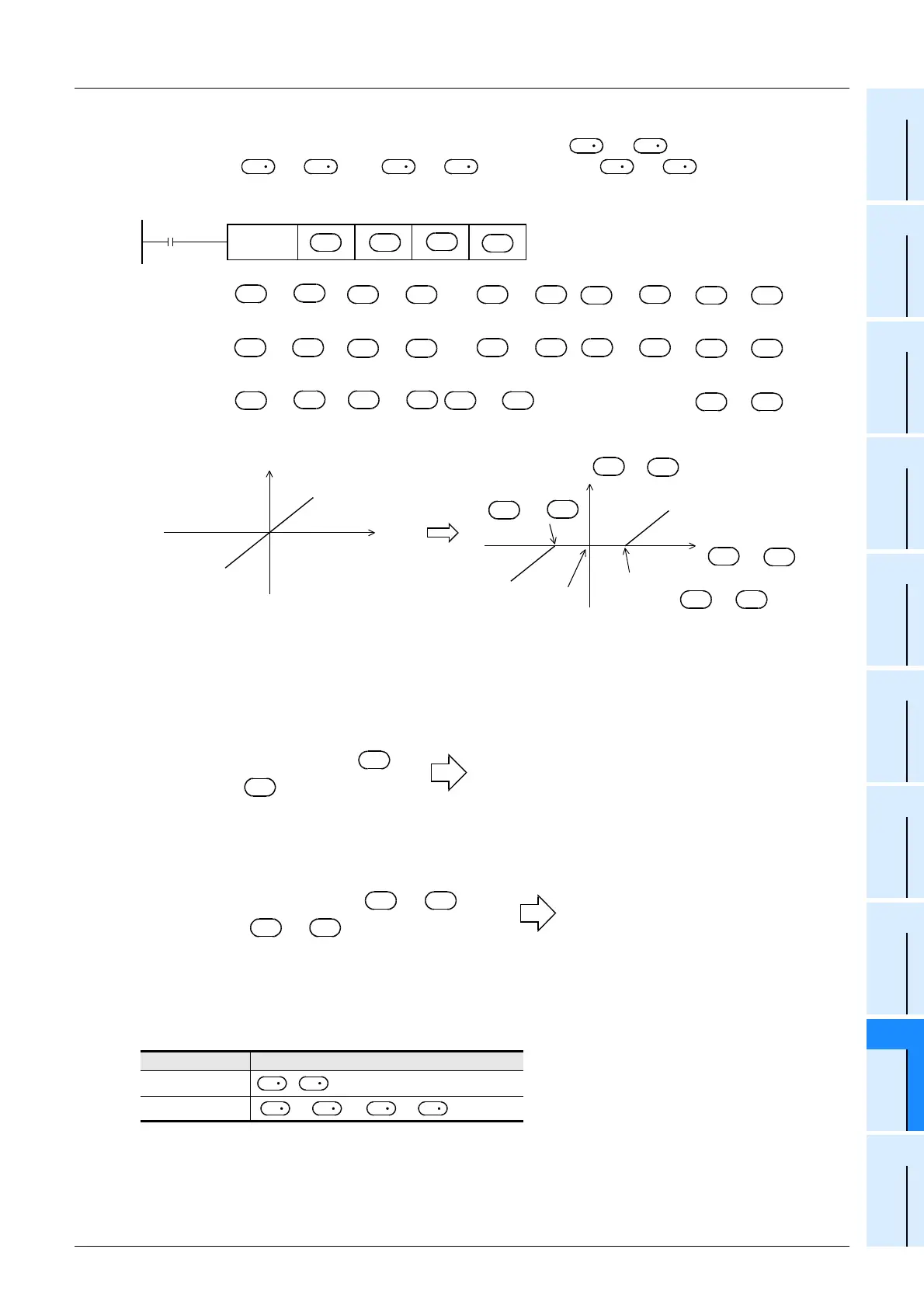
2. 32-bit operation (DBAND and DBANDP)
Depending on how the input value (32-bit binary value) specified by [ +1, ] compares to the dead band
range between [ +1, ] and [ +1, ], the output value [ +1, ] is controlled.
The output value is controlled as shown below:
Caution
• When the output value overflows, it is handled as follows:
- In the 16-bit operation
The output value is a 16-bit binary value with sign. Accordingly, if the operation result is outside the range from
-32768 to +32767, it is handled as follows:
- In the 32-bit operation
The output value is a 32-bit binary value with sign. Accordingly, if the operation result is outside the range from
-2,147,483,648 to +2,147,483,647, it is handled as follows:
Error
An operation error is caused when the instruction is executed in the setting status shown below; The error flag M8067
turns ON, and the error code (K6706) is stored in D8067.
Relationship
16-bit operation
>
32-bit operation
[+1,] > [+1,]
S
3
S
3
S
1
S
1
S
2
S
2
D
D
FNC257
DBAND
+1, +1, +1, +1,
+1, +1, +1, +1,
+1, +1, +1,+1,
+1,
+1,
[]
[]
S
1
S
2
S
3
D
Command
input
In the case of “Lower limit value > Input value” ...............Input value
−
Lower limit value
→
Output value
In the case of “Upper limit value < Input value” ..............Input value
−
Upper limit value
→
Output value
In the case of “Lower limit value
≤
Input value
≤
Upper limit value” ................................ 0
→
Output value
+1,
D
D
+1,
S
3
S
3
Output value
Input
value
Output
value
Input value
S
1
S
1
S
3
S
3
S
2
S
2
S
3
S
3
S
3
S
3
S
1
S
1
S
2
S
2
S
3
S
3
S
3
S
3
S
1
S
1
S
2
S
2
D
D
D
D
D
D
Output
Output
Lower limit value of
dead band
Output value = 0
Upper limit value of
dead band
[]
+1,
S
2
S
2
[]
+1,
S
1
S
1
Lower limit value of dead band = 10
Input value = -32768
Output value = -32768-10
= 8000H-AH
= 7FF6H
= 32758
S
1
S
3
Lower limit value of dead band [ +1, ] = 1000
Input value [ +1, ] = -2,147,483,648
Output value = -2,147,483,648-1000
= 80000000H-000003E8H
= 7FFFFC18H
= 2,147,482,648
S
1
S
3
S
1
S
3
S
1
S
2
S
1
S
1
S
2
S
2

 Loading...


