731
FX3G/FX3U/FX3GC/FX3UC Series
Programming Manual - Basic & Applied Instruction Edition
33 Extension File Register Control – FNC290 to FNC299
33.6 FNC295 – INITER / Initialize ER
31
FNC276-FNC279
Data
Transfer 3
32
FNC280-FNC289
High-Speed
Processing 2
33
FNC290-FNC299
Extension File
Register
34
FNC300-FNC305
FX
3U
-CF-ADP
35
SFC•STL
Programming
36
Interrupt
Function
37
Special Device
38
Error Code
A
Version Up
Information
B
Execution Times
Errors
An operation error is caused in the following cases; The error flag M8067 turns ON, and the error code is stored in
D8067.
• When any device number other than the head device number of a sector of extension file registers (ER) is set to
(error code: K6706)
• When a device number to be initialized exceeds “32767” (error code: K6706)
In this case, devices up to R32767 (ER32767) are initialized.
• When the protect switch of the memory cassette is set to ON (error code: K6770)
• When a memory cassette is not connected (error code: K6771)
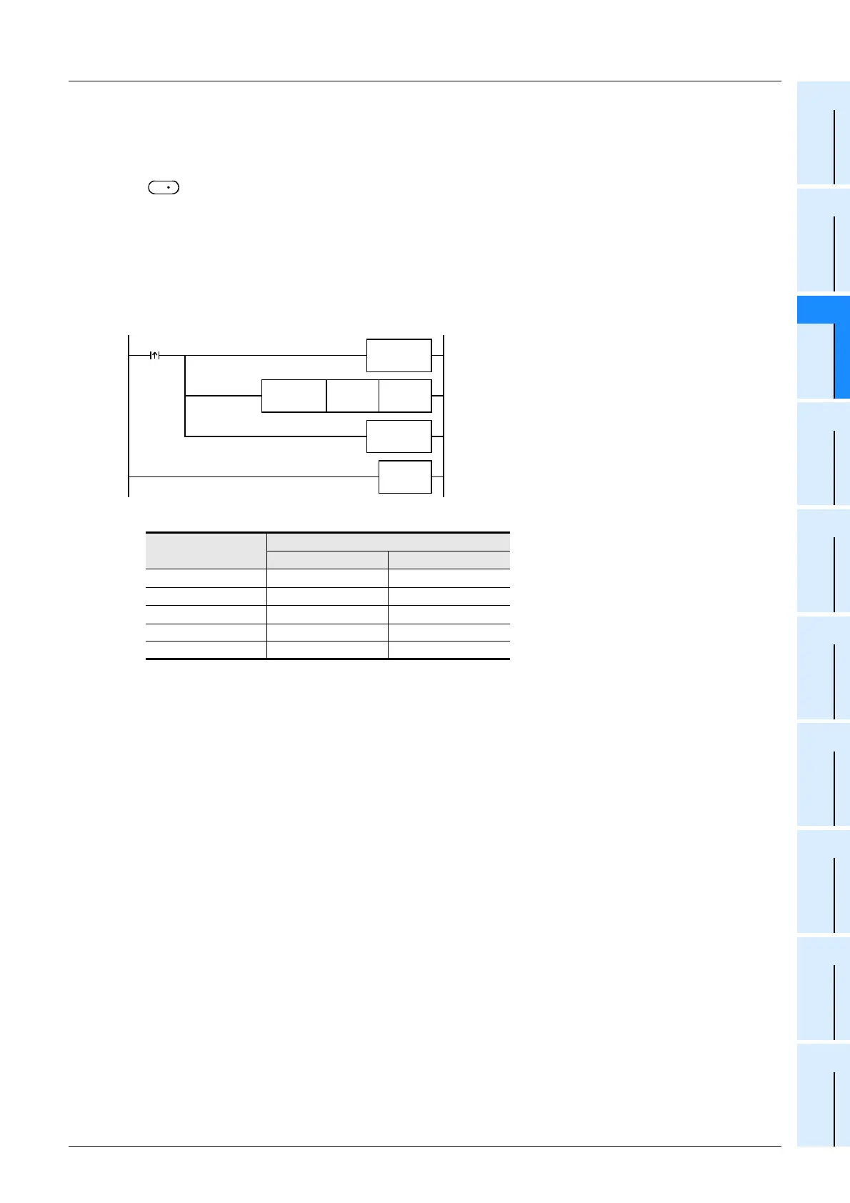
Program example
In the program example shown below, the extension file registers ER0 to ER2047 in sector 0 are initialized.
• Extension file registers (ER) [inside the memory cassette]
Device number
Current value
Before execution After execution
ER0 H1234 HFFFF
ER1 H5678 HFFFF
ER2 H90AB HFFFF
...
...
...
ER2047 HCDEF HFFFF
S
X000
END
R0 K1
FNC 07
WDT
FNC295
INITER
FNC 07
WDT

 Loading...


