757
FX3G/FX3U/FX3GC/FX3UC Series
Programming Manual - Basic & Applied Instruction Edition
35 SFC Program and Step Ladder
35.1 SFC Program
31
FNC276-FNC279
Data
Transfer 3
32
FNC280-FNC289
High-Speed
Processing 2
33
FNC290-FNC299
Extension File
Register
34
FNC300-FNC305
FX
3U
-CF-ADP
35
SFC•STL
Programming
36
Interrupt
Function
37
Special Device
38
Error Code
A
Version Up
Information
B
Execution Times
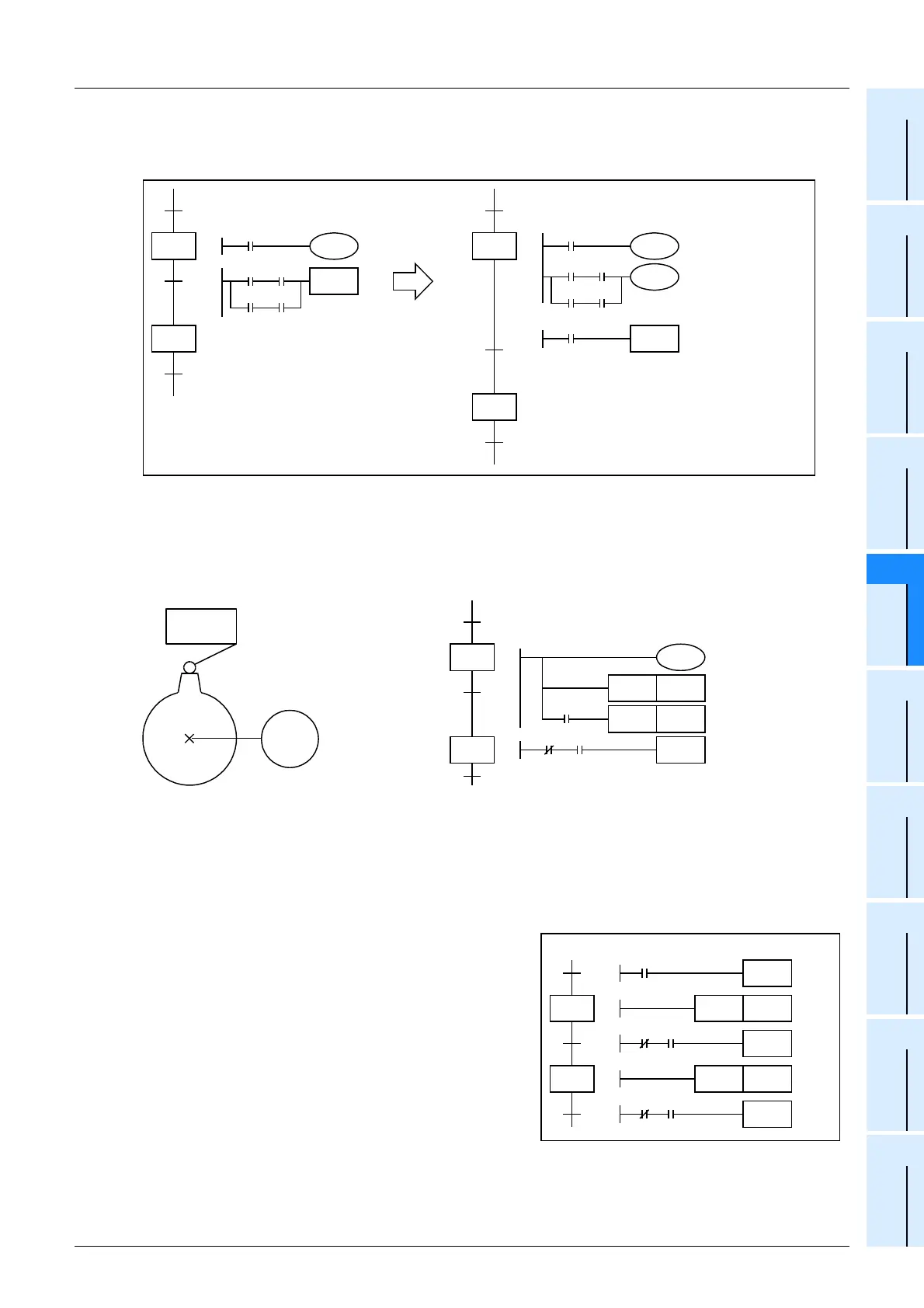
Programming complicated transfer conditions
In a transfer condition circuit, the ANB, ORB, MPS, MRD and MPP instructions are not available.
Program the circuit as shown below:
Processing of state relay whose transfer condition is already satisfied
In some cases, it is necessary to execute the next transfer after the limit switch X030 (working as the transfer
condition) in the ON status is set to OFF once, and then set to ON again.
In such a case, make the transfer condition into pulses as shown below so that transfer is not executed by M100 when
S30 turns ON for the first time.
Transfer of state relay ON status by the same signal
In some cases, it is necessary to transfer the state relay ON status by the ON/OFF operation of one pushbutton
switch.
To achieve such a transfer, it is necessary to convert the transfer signal into pulses in programming.
The following two methods are available to convert the transfer condition into pulses:
1. Procedure using PLS instruction
Immediately after pulse signal M0 turns ON and S50 turns ON,
the transfer condition M1 (NC contact) is open. As a result, it is
not possible to transfer the ON status to S51 at the same time
when S50 turns ON.
When M0 pulse turns ON again, the ON status is transferred to
S51.
Change
31
3
30
Y000
1
2
X004
X000 X001
TRAN
X002 X003
31
3
30
1
2
M0
X000 X001
TRAN
X002 X003
X004
Y000
M0
M
Limit switch
X030
Motor
Forward
rotation Y030
31
30
2
M100
PLS
X030
Y030
M100
PLS M101
M101
TRAN
51
50
M0
M1 M0
1
2
3
TRAN
PLS M1
TRAN
PLS M2
M2 M0
TRAN
Pulse signal

 Loading...


