–
Creating a new program network
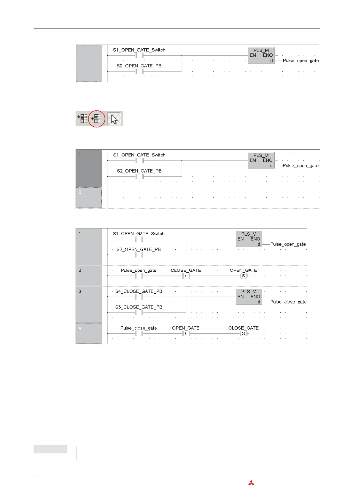
To create a network below the current one, click in the toolbar on this button:
A blank network space will appear:
Enter the following elements in this network and further networks.
All variables except the switches and push buttons are local variables. This already shows the
advantage of using variables with identifiers: Even without entering device comments this pro
-
gram is easier to understand than a program with absolute addresses (e.g. X1, X2 etc.).
쎲
Description of networks 1 to 4
The signals for opening the gate are processed first: When key-operated switch S1 or button
S2 are operated a signal is generated and the variable "Pulse_open_gate" is set to a signal
state of “1” for just one program cycle.This ensures that the gate cannot be blocked if the button
sticks or of the operator does not release it. A similar approach is used to process the signals
from buttons S4 and S5 for closing the gate. It must be ensured that the drive can only be
switched on when it is not already turning in the opposite direction. This is implemented by pro
-
gramming the PLC so that the gate can only be closed when it is not opening and vice versa.
NOTE The motor direction interlock must also be complemented by an additional interlock with
physical contactors outside the PLC (see wiring diagram in chapter 4.9.3.).
4–42 MITSUBISHI ELECTRIC
Programming PLC Applications An Introduction to Programming

 Loading...


