4.5.2 Graphic Editors
Ladder Diagram
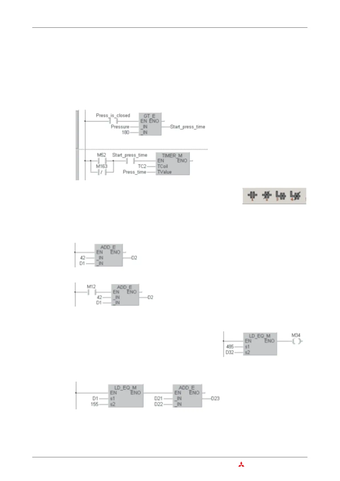
Programming in Ladder Diagram is very similar to drawing a circuit diagram for conventional
relay systems. A Ladder Diagram consists of input contacts (makers and breakers), output
coils but also function blocks and functions. These elements are connected with horizontal
and vertical lines to create circuits.The circuits always begins at the bus bar (power bar) on the
left.
More complex function and function blocks are displayed as boxes in a Ladder Diagram. In
addition to the inputs and output necessary for the function function and function blocks have
an EN input and an ENO output. The EN input (EN = ENable) controls the execution of the
instruction.
The result of the operation is passed to the ENO output (ENO = ENable Out).
To control the program flow, ENO outputs and EN inputs can be connected. In the following
example the execution of the second instruction depends on the result of the first instruction.
4–8 MITSUBISHI ELECTRIC
Programming Languages An Introduction to Programming
Example for Ladder Diagram
This instruction is executed cyclical.
This instruction is only executed when M12 is ON.
M34 is set when the contents of the two devices compared
with the compare instruction are identical.
For the most frequently applied instructions in Ladder Diagram
buttons are available in the toolbar.

 Loading...


