The following table shows the extension possibilities and the number of inputs and outputs for
the PLC CPUs.
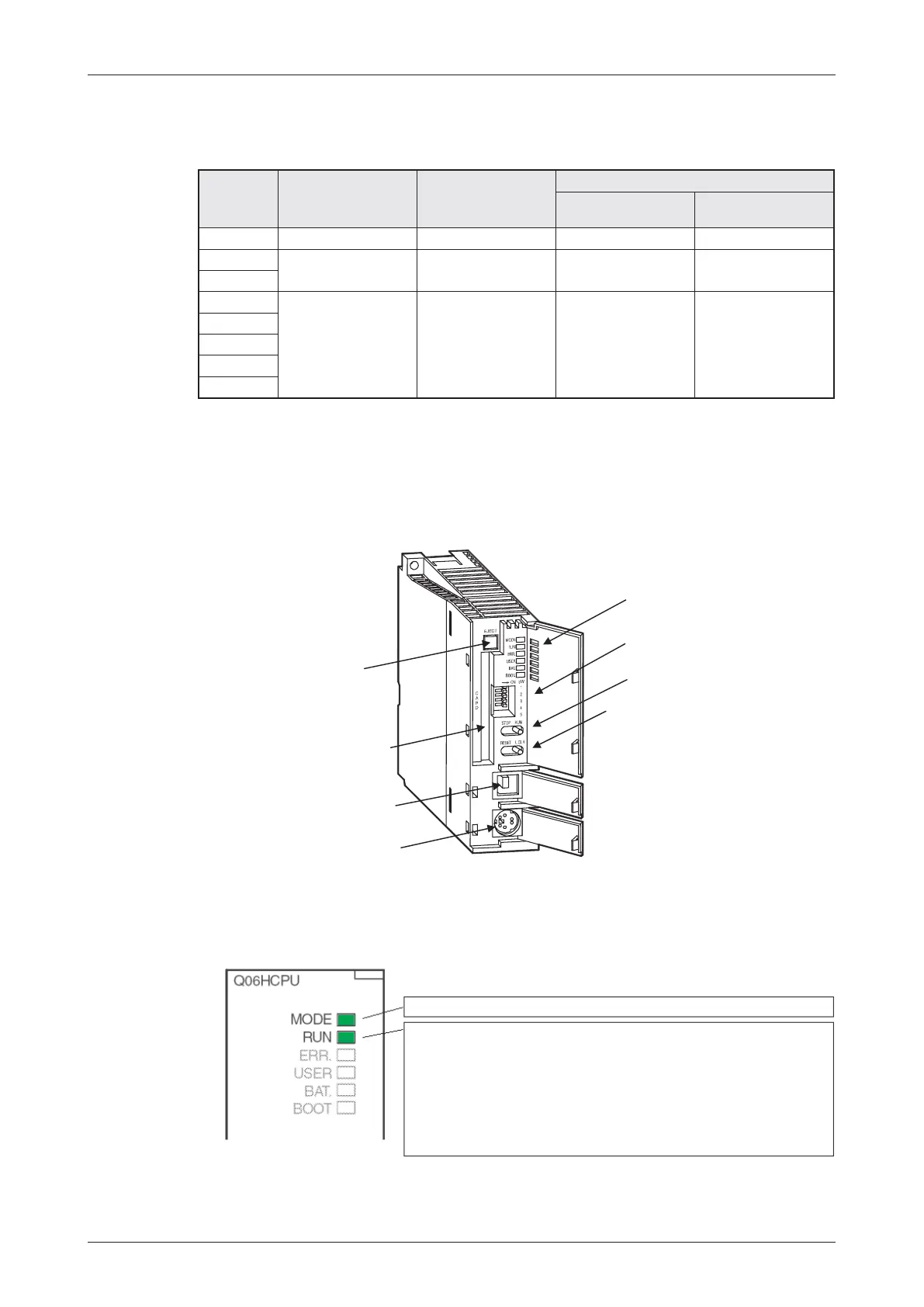
3.4.1 Part Names of CPU Modules
LED Display
–
MODE- und RUN-LED
MELSEC System Q Beginners Manual 3 – 9
The MELSEC System Q The CPU Modules
Green: Q mode
ON: During operation in “RUN“ mode
OFF: During “STOP“ mode or after detection of an
error occurrence that stopped the operation
Flicker: RUN/STOP switch was switched from “STOP“ to
“RUN“ after a program or a parameter was written
during “STOP“. The CPU is not in “RUN“ mode.
Memory card
eject button
Memory card loading
connector
USB connector (not for Q00,
Q01 and Q02CPU)
RS232 connector
Switches fpr system settings
RUN/STOP switch
RESET/L.CLR switch
(For Q00CPU and Q01CPU the RESET
switch is combined with the RUN/STOP
switch.)
LED display
CPU
Module
Number of
connectable
extension base units
Number of modules
to be installed
Number of I/O points
Local (on main and
extension base units)
Remote
Q00JCPU 2 16 256 2048
Q00CPU
4 24 1024 2048
Q01CPU
Q02CPU
7 64 4096 8192
Q02HCPU
Q06HCPU
Q12HCPU
Q25HCPU

 Loading...


