3.5.1 Digital Input Modules
Input modules are available for various input voltages:
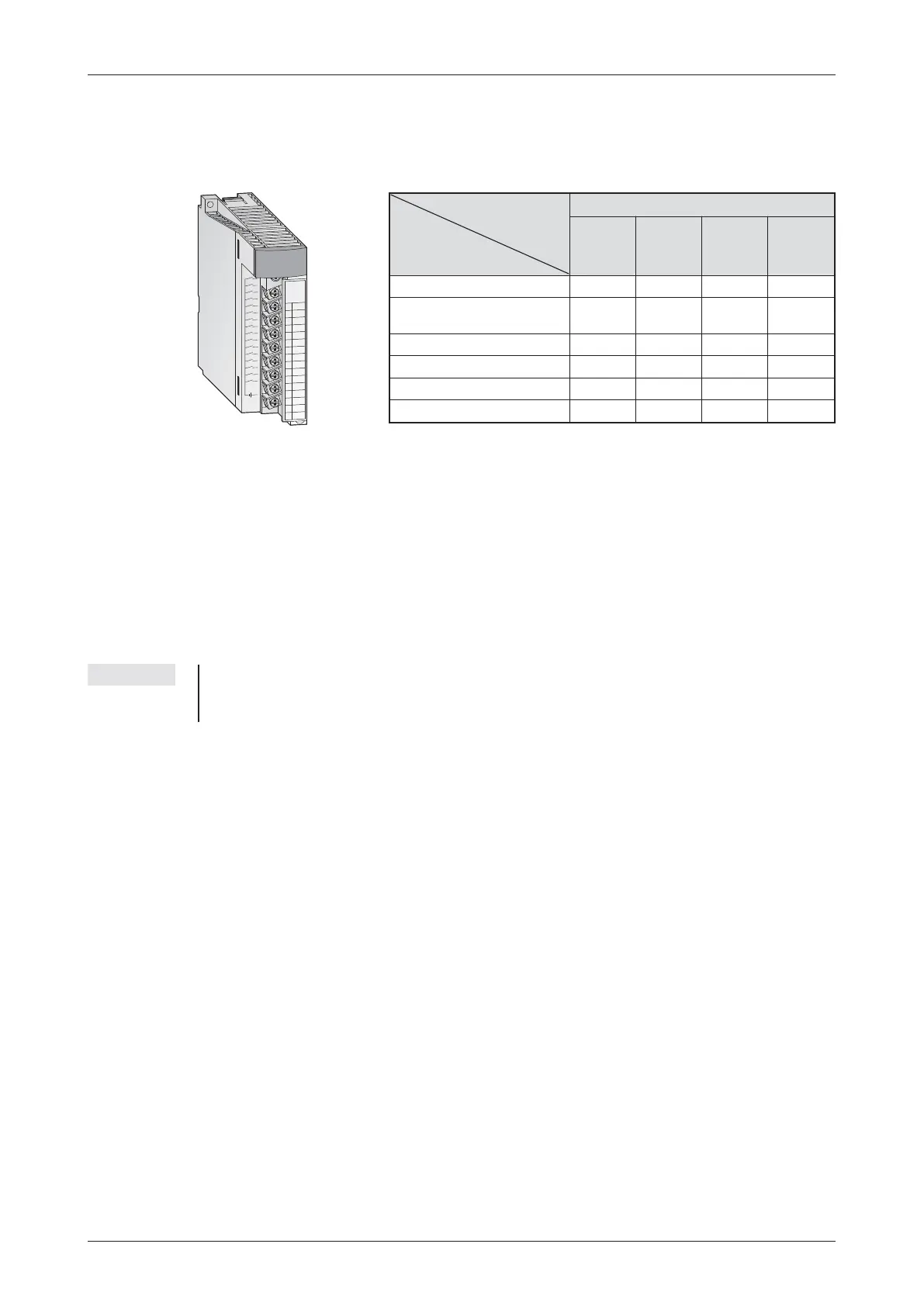
Modules with 8 or 16 connection points provide removable screw terminal blocks.The modules
with 32 or 64 connection points are connected via a plug.
General PLC input considerations
All inputs are isolated by opto-couplers.This prevents the sensitive CPU electronics in the PLC
from being affected by electrical noise spikes induced by external equipment.
Another common problem is contact bounce generated by electromechanical switches. To
avoid the PLC from being affected by these parasitic effects, the inputs are filtered so that the
On/Off status will register an "ON" state only if the signal is stable for a period exceeding the fil-
ter coefficient
NOTE The filter coefficient of the standard input modules is preset to 10 ms but may be individually
adjusted in the range of 1 ms to 70 ms from within the parameter setup of the CPU (See indi-
vidual module specifications).
This filter response time should be taken into account when programming as it will have a
direct effect on the way the program will operate. If higher speed input functionality is utilised
where the input filter coefficient is reduced, care should be taken when using these inputs for
digital signalling. Cables should be shielded and run separately to other potential sources of
electrical noise! If very high speed operation is required within the system then special mod-
ules such as the interrupt module QI60 should be adopted.
For the PLC to register a logical change in input condition, a minimum current has to flow
through this input.This minimum current depends on the type of input module used and is 3 mA
in most of the cases. Anything less than this will result in the input not turning on, even when a
sensor connected to the input is switched on. The input current is limited by the input resis-
tance.If the input voltage is higher than the rated voltage, the input current also increases. The
input will accept up toa7mAsignal, anything in excess of this could result in the input being
damaged.
The PLC CPU polls the signal states of the inputs at the beginning of each program cycle and
stores them. In the program the CPU accesses the stored states of the inputs. The stored
states are updated again before the next program cycle is executed.
MELSEC System Q Beginners Manual 3 – 17
Digital Input and Output Modules Das MELSEC System Q
0
1
3
5
7
9
B
D
F
2
4
6
8
A
C
E
NC
24VDC
4mA
COM
1
2
3
4
5
6
7
8
9
A
B
C
D
E
F
Q
X
8
0
01234567
89ABC D EF
Input module of MELSEC System Q
No. of
Inputs
8 163264
Input voltage
5 – 12 V DC QX70 QX71 QX72
24 V DC
QX40
QX80
QX41
QX81
QX42
QX82
24 V DC (Interrupt module) QI60
48 V AC/DC QX50
100 – 120 V AC QX10
100 – 240 V AC QX28

 Loading...


