4.7.1 Starting logic operations
A circuit in a program always begins with an LD- or LDI instruction. These instructions can be
performed on inputs, relays, timers and counters.
For examples of using these instructions see the description of the OUT instruction in the next
section.
4.7.2 Outputting the result of a logic operation
The OUT instruction can be used to terminate a circuit. You can also program circuits that use
multiple OUT instructions as their result. This is not necessarily the end of the program, how-
ever. The device set with the result of the operation using OUT can then be used as an input
signal state in subsequent steps of the program.
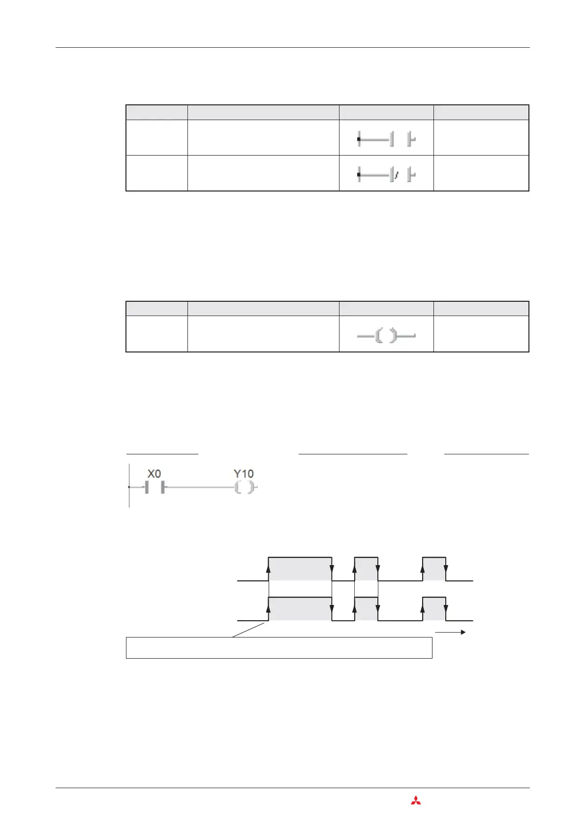
Example (LD and OUT instructions)
These two instructions result in the following signal sequence:
4–14 MITSUBISHI ELECTRIC
The Basic Instruction Set An Introduction to Programming
Instruction Function Ladder Diagram IEC Instruction List
OUT
Output instruction, assigns the result of
an operation to a device
ST
Ladder Diagram
MELSEC Instruction List
LD X0
OUT Y10
IEC Instruction List
LD X0
ST Y10
Y10
X0
OFF
ON
OFF
ON
t
(0)
(1)
(0)
(1)
The condition of the LD instruction (poll for signal state “1”) is true so the result of the
operation is also true (“1”) and the output is set.
Instruction Function Ladder Diagram IEC Instruction List
LD
Load instruction, starts a logic operation
and polls the specified device for signal
state “1”
LD
LDI
Load instruction, starts a logic operation
and polls the specified device for signal
state “0”
LDN

 Loading...


