3.5 Digital Input and Output Modules
Input and output modules connect a PLC CPU with the process to be controlled. The digital
inputs are used for inputting control signals from the connected switches, buttons or sensors.
These inputs can read the values ON (power signal on) and OFF (no power signal). Digital out
-
put modules can switch external actuators ON or OFF.
The input signals can come from a wide variety of devices i.e.
쎲 Push buttons.
쎲 Rotary switches.
쎲 Key switches.
쎲 Limit switches.
쎲 Level sensors.
쎲 Flow rate sensors
쎲 Photo-electric detectors.
쎲 Proximity detectors (inductive or capacitive).
Proximity detectors usually provide a transistor output which can be either an NPN (sink)
or PNP (source) transistor.
Output signals forexampleareusedtocontrol:
쎲 Relays and contactors
쎲 Signal lamps
쎲 Solenoids
쎲 Inputs of other devices e. g. inverters.
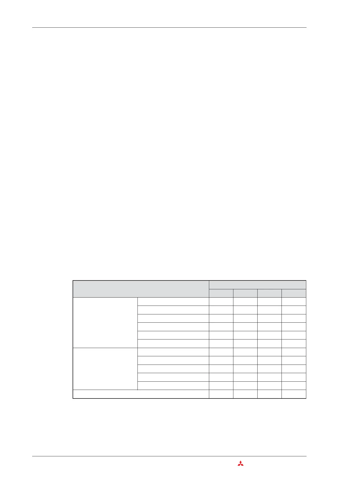
Overview of digital I/O module types
쎲
= Module is available
쑗
= Module is not available
3–16 MITSUBISHI ELECTRIC
Das MELSEC System Q Digital Input and Output Modules
Type
Number of inputs/outputs
8 163264
Input modules
120 V AC
쑗쎲쑗쑗
240 V AC
쎲쑗쑗쑗
48 V AC/DC
쑗쎲쑗쑗
24 V DC
쑗쎲쎲쎲
24 V DC (High speed)
쎲쑗쑗쑗
5 V DC / 12 V DC
쑗쎲쎲쎲
Output modules
Relays
쎲쎲쑗쑗
Individual relay
쎲쑗쑗쑗
Triac output
쑗쎲쑗쑗
Transistor output (sink)
쎲쎲쎲쎲
Transistor output (source)
쑗쎲쎲쑗
Combined input/output modules
쎲쑗쎲쑗

 Loading...


