5.2 Relays
In your PLC programs you will often need to store intermediate binary results (a signal state of
“0” or “1”) temporarily for future reference. The PLC has special memory cells available for this
purpose known as “auxiliary relays”, or “relays” for short (device identifier: "M").
You can store the binary result of an operation in a relay, for example with an OUT instruction,
and then use the result in future operations. Relays help to make programs easier to read and
also reduce the number of program steps: You can store the results of operations that need to
be used more than once in a relay and then poll it is often as you like in the rest of the program.
In addition to normal relays the controllers of the MELSEC System Q also have retentive or
“latched” relays. The normal unlatched relays are all reset to a signal state of “0” when the PLC
power supply is switched off, and this is also their standard state when the controller is
switched on. In contrast to this, latched relays retain their current states when the power is
switched off and on again.
*
You can set the number of latched and unlatched relays with the PLC parameters. The values shown above are the
initial settings.
5–4 MITSUBISHI ELECTRIC
Relays Devices in Detail
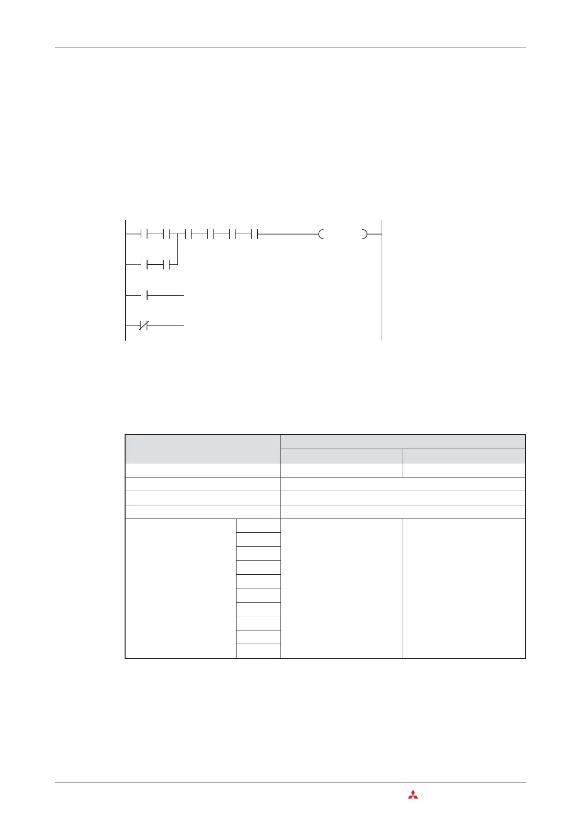
M1
M1
M1
Poll for signal state “1” (relay set)
Poll for signal state “0” (has the relay been reset?)
Device
Relay types
Unlatched relays Latched relays
Device identifier M L
Device type Bit device
Possible values for a device 0 or 1
Device address format Decimal
Number of devices and
addresses
Q00J
8192 (M0–M8191)* 8192 (L0–L8191)*
Q00
Q01
Q02
Q02H
Q06H
Q12H
Q25H
Q12PH
Q25PH

 Loading...


