4.7.3 Using switches and sensors
Before we continue with the description of the rest of the instructions we should first describe
how signals from switches, sensors and so on can be used in your programs.
PLC programs need to be able respond to signals from switches, buttons and sensors to per
-
form the correct functions. It is important to understand that program instructions can only poll
the binary signal state
of the specified input – irrespective of the type of input and how it is
controlled.
Usually, switches with make contacts are used. Sometimes, however, break contacts are used
for safety reasons – for example for switching off drives (see section 4.8).
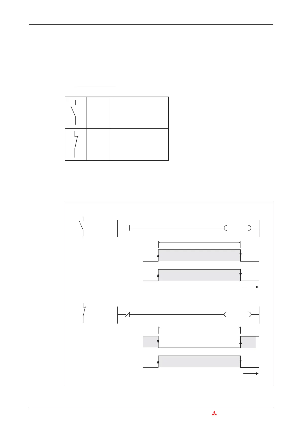
The illustration below shows two program sequences in which the result is exactly the same,
even though different switch types are used: When the switch is operated the output is set
(switched on).
4–16 MITSUBISHI ELECTRIC
The Basic Instruction Set An Introduction to Programming
Normally
open con
-
tact (make
contact)
When a make normally open
contact is operated the input
is set (ON, signal state “1”)
Normally
closed
contact
(break
contact)
When a normally closed con
-
tact is operated the input is
reset (OFF, signal state “0”)
As you can imagine, this means that when
you are writing your program you need to be
aware whether the element connected to the
input of your PLC is a make or a break device.
An input connected to a make device must be
treated differently to an input connected to a
break device. The following example illustra
-
tes this.
Y010
X000
24 V
X0
Y10
X0
OFF
ON
OFF
ON
t
Y010
X000
24 V
X0
Y10
X0
OFF
ON
OFF
ON
t
Switch operated
Switch operated
 Loading...


