EasyManua.ls Logo

Mitsubishi MELSEC System Q User Manual

Mitsubishi MELSEC System Q
170 pages
To Next Page IconTo Next Page
To Previous Page IconTo Previous Page
Page #157 background imageLoading...
Page #157 background image
6.4 Math Instructions
All the controllers of the MELSEC System Q can perform all four basic arithmetical operations
and can add, subtract, multiply and divide. MELSEC instructions are available for math opera
-
tions with binary values, binary block data, BCD values and character strings.
When you edit your program with GX IEC Developer in Ladder Diagram or IEC instruction list
additional IEC instructions can be used. In this chapter only these IEC instructions are
described. MELSEC instructions are covered in detail in the Programming Manual for the A/Q
series and the MELSEC System Q, art. no. 87431.
The IEC instructions for addition, subtraction, multiplication und division can be applied for the
data types INT (16-bit integer), DINT (32-bit integer) or REAL (floating decimal point values).
Please note that DINT and REAL devices can not assigned directly to these instructions and
must be defined as variables before (see chapter 4.6.2).
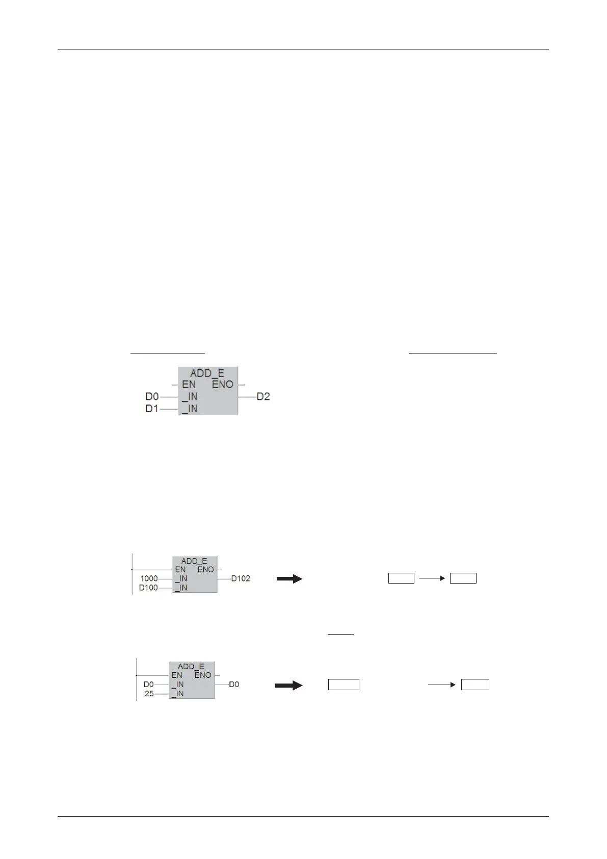
6.4.1 Addition
The ADD instruction calculates the sum of two values and writes the result to another device.
First source device or constant
Second source device or constant
Device in which the result of the addition is stored
The example above adds the contents of D0 and D1 and writes the result to D2.
Examples
Add 1,000 to the contents of data register D100:
If you want you can also write the result to one of the source devices. However, if you do this
remember that the result will then change in every
program cycle if the ADD instruction is exe
-
cuted cyclically!
The signs of the values are taken into account by the ADD instruction (e. g. 10 + (-5) = 5).
The data types of the input and output variable of the ADD instruction must be identical. This
can cause problems when the result of the addition exceeds the value range of the variables.
For example, when you add the two integer values (16 bit) "32700" and "100" the result stored
is not "32800" as expected but "-32736" since the maximum value of a 16 bit variable is
"32767". An overflow is interpreted as negative value and will lead to a wrong result.
MELSEC System Q Beginners Manual 6 25
More Advanced Programming Math Instructions
Ladder Diagram
IEC Instruction List
LD D0
ADD D1
ST D2
1000
53+
D 100
D 102
1053
18
25
D 0
+
D 0
43

Table of Contents

Other manuals for Mitsubishi MELSEC System Q

Question and Answer IconNeed help?

Do you have a question about the Mitsubishi MELSEC System Q and is the answer not in the manual?

Mitsubishi MELSEC System Q Specifications

General IconGeneral
CategoryProgrammable Logic Controller (PLC)
TypeModular
SeriesMELSEC
I/O CapacityUp to 4096 points
Programming LanguagesLadder Logic, Structured Text, Function Block Diagram, Instruction List, Sequential Function Chart
Communication ProtocolsEthernet, CC-Link
RedundancyAvailable in certain models
Power Supply24 V DC, 100-240 V AC (depending on the power supply module)
Operating Temperature0°C to 55°C
Storage Temperature-25°C to 75°C
Humidity5% to 95% (non-condensing)
Shock Resistance147 m/s2 acceleration, 3 times in each of the X, Y, and Z directions
CPU TypeVarious CPUs available (e.g., Q00, Q01, Q02, Q06, Q12, Q13, Q26, Q100, Q172, Q173)

Summary

2 Programmable Logic Controllers

3 The MELSEC System Q

3.1 System Configuration

Details the modular structure and components of the MELSEC System Q.

3.2 Base Units

Describes available base units for mounting MELSEC System Q modules.

3.3 Power Supply Modules

Explains the function and types of power supply modules for MELSEC System Q.

3.4 The CPU Modules

Introduces different types of CPU modules available for the MELSEC System Q.

3.5 Digital Input and Output Modules

Describes the types and functions of digital input and output modules.

3.5.1 Digital Input Modules

Explains the specifications and considerations for digital input modules.

3.5.2 Digital Output Modules

Details the types, advantages, and specifications of digital output modules.

3.6 Special Function Modules

Introduces various special function modules for MELSEC System Q automation.

3.6.1 Analog Modules

Explains analog input and output modules and selection criteria.

3.7 Networks and Network Modules

Covers networking concepts and modules for MELSEC System Q communication.

3.7.4 Network Modules

Explains ETHERNET and MELSECNET modules for system communication.

4 An Introduction to Programming

4.7 The Basic Instruction Set

Provides a reference to basic instructions used in MELSEC PLC programming.

4.8 Safety First!

Emphasizes crucial safety precautions when working with PLCs and systems.

4.9 Programming PLC Applications

Demonstrates PLC application development with a practical example.

4.9.1 A rolling shutter gate

Presents a detailed example of programming a rolling shutter gate control system.

4.9.2 Programming

Guides through the process of creating a new PLC project and assigning variables.

5 Devices in Detail

5.1 Inputs and Outputs

Explains how PLC inputs and outputs connect to the controlled process.

5.2 Relays

Details the function and types of relays (normal and latched) in PLC programs.

5.3 Timers

Describes programmable internal timers, their function, and types (low/high speed, retentive).

5.4 Counters

Explains internal counters for programming counting operations and their features.

5.5 Registers

Covers registers for storing measurements and calculation results (16-bit and 32-bit).

5.5.1 Data registers

Details data registers used for memory storage in PLC programs.

6 More Advanced Programming

6.1 Applied Instructions Reference

Provides a reference for advanced PLC instructions beyond basic logic.

6.2 Instructions for Moving Data

Explains instructions for moving data between registers and devices.

6.2.5 Exchanging data with special function modules

Details using FROM/TO instructions for data exchange with special function modules.

6.3 Compare Instructions

Explains instructions for comparing values (numerical, string) in PLC programs.

6.4 Math Instructions

Covers basic arithmetic operations like addition, subtraction, multiplication, and division.

Related product manuals