4.7.9 Generating pulses
*
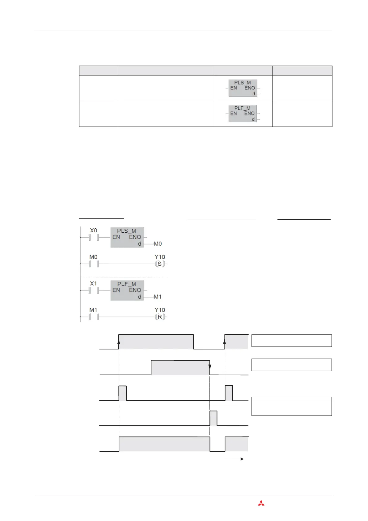
PLC and PLF instructions can be used to set outputs (Y) and relays (M).
These instructions effectively convert a static signal into a brief pulse, the duration of which
depends on the length of the program cycle. If you use PLS instead of an OUT instruction the
signal state of the specified device will only be set to “1” for a single program cycle, specifically
during the cycle in which the signal state of the device before the PLS instruction in the circuit
switches from “0” to “1” (rising edge pulse).
The PLF instruction responds to a falling edge pulse and sets the specified device to “1” for a
single program cycle, during the cycle in which the signal state of the device before the PLF
instruction in the circuit switches from “1” to “0” (falling edge pulse).
4–28 MITSUBISHI ELECTRIC
The Basic Instruction Set An Introduction to Programming
Instruction Function Ladder Diagram IEC Instruction List
PLS
Pulse, sets an device* for the duration of
a single program cycle on the rising edge
of the switching pulse of the input condi
-
tion / device
PLS_M
PLF
Pulse Falling, sets a device* for the dura
-
tion of a single program cycle on the fall
-
ing edge of the switching pulse of the
input condition / device
PLF_M
Ladder Diagram
MELSEC Instruction List
LD X0
PLS M0
LD M0
SET Y10
LD X1
PLF M1
LD M1
RST Y10
IEC Instruction List
LD X0
PLS_M M0
LD M0
SY10
LD X1
PLF_M M1
LD M1
RY10
M1
X1
M0
Y10
X0
t
The rising edge of the device X0
signal triggers the function.
Relays M0 and M1 are only
switched on for the duration of a
single program cycle.
In the case of device X1 the falling
edge of the signal is the trigger.

 Loading...


