EasyManua.ls Logo

Mitsubishi MELSEC System Q User Manual

Mitsubishi MELSEC System Q
170 pages
To Next Page IconTo Next Page
To Previous Page IconTo Previous Page
Page #126 background imageLoading...
Page #126 background image
5.6 Constants
5.6.1 Decimal and Hexadecimal constants
Decimal and hexadecimal constants are devices which designate decimal resp. hexadecimal
data in sequence programs (e. g. setpoints for Timer and Counter). The constant is converted
by the PLC CPU into a binary number.
Decimal constants are not particularly denoted in the Ladder Diagram or the IEC instruction
list. Hexadecimal constants are prefixed with "16#". For example the notation 16#12 is inter
-
preted by the PLC CPU as hexadecimal value 12.
In the MELSEC instruction list decimal constants are prefixed with the letter "K" and hexadeci
-
mal constants are prefixed with the letter "H". Examples: K100 = decimal value 100; K64 = hex
-
adecimal value 64.
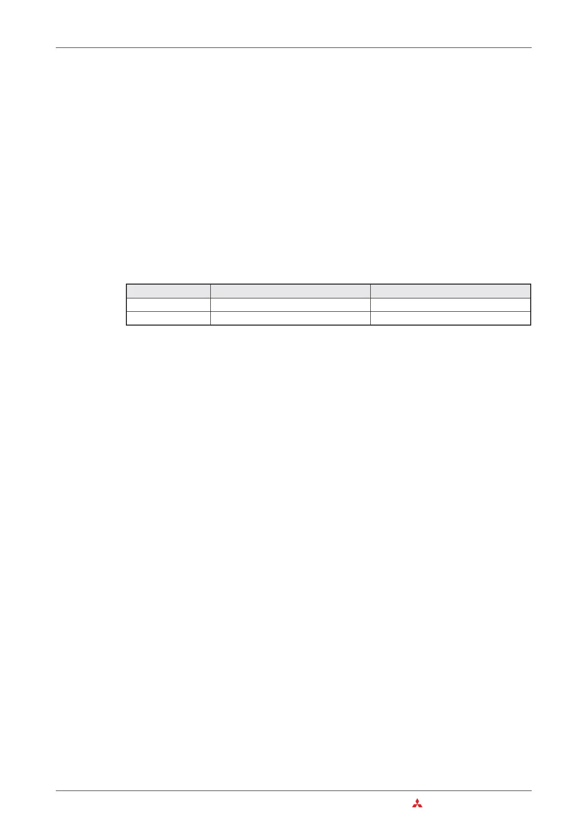
The following table shows the value ranges of the decimal and hexadecimal constants
5.6.2 Floating decimal point constants
Decimal constants are integer values.Floating decimal point values (or real numbers) however
have decimal places and therefore offer advantages for arithmetical operations.
Floating decimal point constants are prefixed by an "E" in the sequence program (for example
E1.234 or E1.234 + 3). As you see, these constants can be designated in the program by an
expression with or without exponent.
Designation of a constant without exponent
The specified value is designated in the "normal" way. For example 10.2345 becomes
"E10.2345".
Designation of a constant with exponent
The value is divided into a base and an exponent.The base of the exponent is 10 (10
n
).For
example, 1234 can be expressed as 1.234 x 1000 or in exponential expression as
1.234 x 10
3
.In the sequence program this value becomes E1.234 + 3.(+3 represents 10
3
).
The value ranges for floating decimal point constants are:
-1.0 x 2
128
to -1.0 x 2
-126
,
0
and 1.0 x 2
-126
to 1.0 x 2
+128
5.6.3 Character string constants
When characters are designated in the sequence program by quotation marks they are inter
-
preted as ASCII code (e. g. "MOTOR12").One character occupies 1 byte.You can use up to 32
characters for a character string.
5–14 MITSUBISHI ELECTRIC
Constants Devices in Detail
Constants 16 bit 32 bit
Decimal
-32 768 to +32 767 -2 147 483 648 to +2 147 483 647
Hexadecimal
0 to FFFF 0 to FFFFFFFF

Table of Contents

Other manuals for Mitsubishi MELSEC System Q

Question and Answer IconNeed help?

Do you have a question about the Mitsubishi MELSEC System Q and is the answer not in the manual?

Mitsubishi MELSEC System Q Specifications

General IconGeneral
CategoryProgrammable Logic Controller (PLC)
TypeModular
SeriesMELSEC
I/O CapacityUp to 4096 points
Programming LanguagesLadder Logic, Structured Text, Function Block Diagram, Instruction List, Sequential Function Chart
Communication ProtocolsEthernet, CC-Link
RedundancyAvailable in certain models
Power Supply24 V DC, 100-240 V AC (depending on the power supply module)
Operating Temperature0°C to 55°C
Storage Temperature-25°C to 75°C
Humidity5% to 95% (non-condensing)
Shock Resistance147 m/s2 acceleration, 3 times in each of the X, Y, and Z directions
CPU TypeVarious CPUs available (e.g., Q00, Q01, Q02, Q06, Q12, Q13, Q26, Q100, Q172, Q173)

Summary

2 Programmable Logic Controllers

3 The MELSEC System Q

3.1 System Configuration

Details the modular structure and components of the MELSEC System Q.

3.2 Base Units

Describes available base units for mounting MELSEC System Q modules.

3.3 Power Supply Modules

Explains the function and types of power supply modules for MELSEC System Q.

3.4 The CPU Modules

Introduces different types of CPU modules available for the MELSEC System Q.

3.5 Digital Input and Output Modules

Describes the types and functions of digital input and output modules.

3.5.1 Digital Input Modules

Explains the specifications and considerations for digital input modules.

3.5.2 Digital Output Modules

Details the types, advantages, and specifications of digital output modules.

3.6 Special Function Modules

Introduces various special function modules for MELSEC System Q automation.

3.6.1 Analog Modules

Explains analog input and output modules and selection criteria.

3.7 Networks and Network Modules

Covers networking concepts and modules for MELSEC System Q communication.

3.7.4 Network Modules

Explains ETHERNET and MELSECNET modules for system communication.

4 An Introduction to Programming

4.7 The Basic Instruction Set

Provides a reference to basic instructions used in MELSEC PLC programming.

4.8 Safety First!

Emphasizes crucial safety precautions when working with PLCs and systems.

4.9 Programming PLC Applications

Demonstrates PLC application development with a practical example.

4.9.1 A rolling shutter gate

Presents a detailed example of programming a rolling shutter gate control system.

4.9.2 Programming

Guides through the process of creating a new PLC project and assigning variables.

5 Devices in Detail

5.1 Inputs and Outputs

Explains how PLC inputs and outputs connect to the controlled process.

5.2 Relays

Details the function and types of relays (normal and latched) in PLC programs.

5.3 Timers

Describes programmable internal timers, their function, and types (low/high speed, retentive).

5.4 Counters

Explains internal counters for programming counting operations and their features.

5.5 Registers

Covers registers for storing measurements and calculation results (16-bit and 32-bit).

5.5.1 Data registers

Details data registers used for memory storage in PLC programs.

6 More Advanced Programming

6.1 Applied Instructions Reference

Provides a reference for advanced PLC instructions beyond basic logic.

6.2 Instructions for Moving Data

Explains instructions for moving data between registers and devices.

6.2.5 Exchanging data with special function modules

Details using FROM/TO instructions for data exchange with special function modules.

6.3 Compare Instructions

Explains instructions for comparing values (numerical, string) in PLC programs.

6.4 Math Instructions

Covers basic arithmetic operations like addition, subtraction, multiplication, and division.

Related product manuals