4.7.6 Instructions for connecting operation blocks
Although ANB- and ORB are PLC instructions they are only displayed and entered as connect
-
ing lines in the Ladder Diagram display. They are only shown as instructions in Instruction List
format, where you must enter them with their acronyms ANB and ORB.
Both instructions are entered without devices and can be used as often as you like in a pro
-
gram. However, the maximum number of LD and LDI instructions is restricted to 15, which
effectively also limits the number of ORB or ANB instructions you can use before an output
instruction to 15 as well.
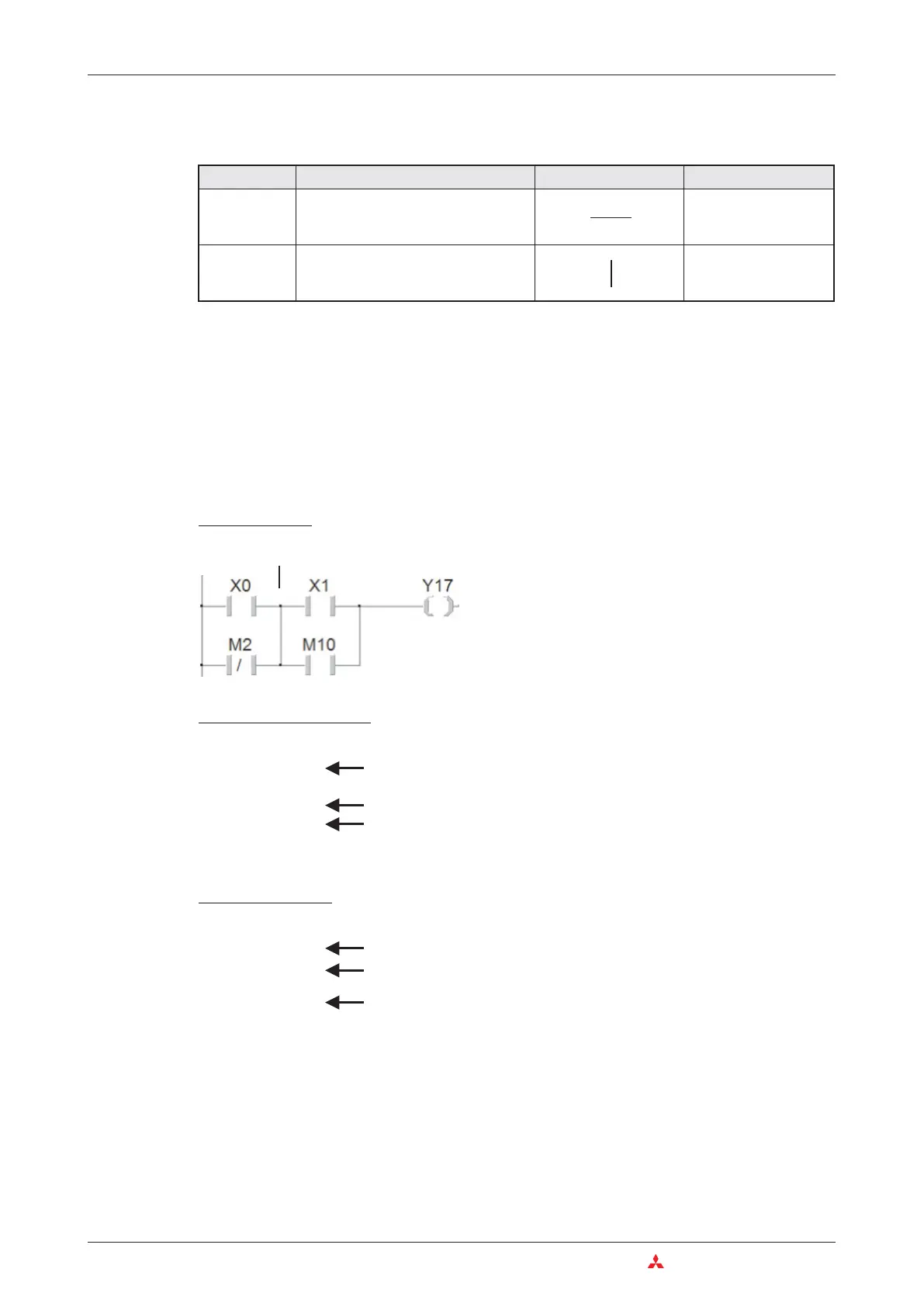
Example of an ANB instruction
In this example output Y17 is switched on if input X00 is “1” and input X01 is “0”, or if relay M2 is
“0” and relay M10 is “1”.
4–20 MITSUBISHI ELECTRIC
The Basic Instruction Set An Introduction to Programming
Instruction Function Ladder Diagram IEC Instruction List
ANB
AND Block (serial connection of blocks of
parallel operations/circuits)
AND (
... )
ORB
OR Block (parallel connection of blocks
of serial operations/circuits)
OR (
... )
LD X0
ORI M2
LD X1
OR M10
ANB
OUT Y17
MELSEC Instruction List
Ladder Diagram
ANB instruction
1
st
parallel connection (OR operation)
2
nd
parallel connection (OR operation)
ANB instruction connecting both OR operations
LD X0
ORN M2
AND(
X1
OR M10
)
ST Y017
IEC Instruction List
1
st
parallel connection (OR operation)
2
nd
parallel connection (OR operation)
ANB instruction connecting both OR operations

 Loading...


