EasyManua.ls Logo

Mitsubishi MELSEC System Q User Manual

Mitsubishi MELSEC System Q
170 pages
To Next Page IconTo Next Page
To Previous Page IconTo Previous Page
Page #66 background imageLoading...
Page #66 background image
4.2 Bits, Bytes and Words
As in all digital technology, the smallest unit of information in a PLC is a “bit”.A bit can only have
two states: “0” (OFF or FALSE) and “1” (ON or TRUE). PLCs have a number of so-called bit
devices that can only have two states, including inputs, outputs and relays.
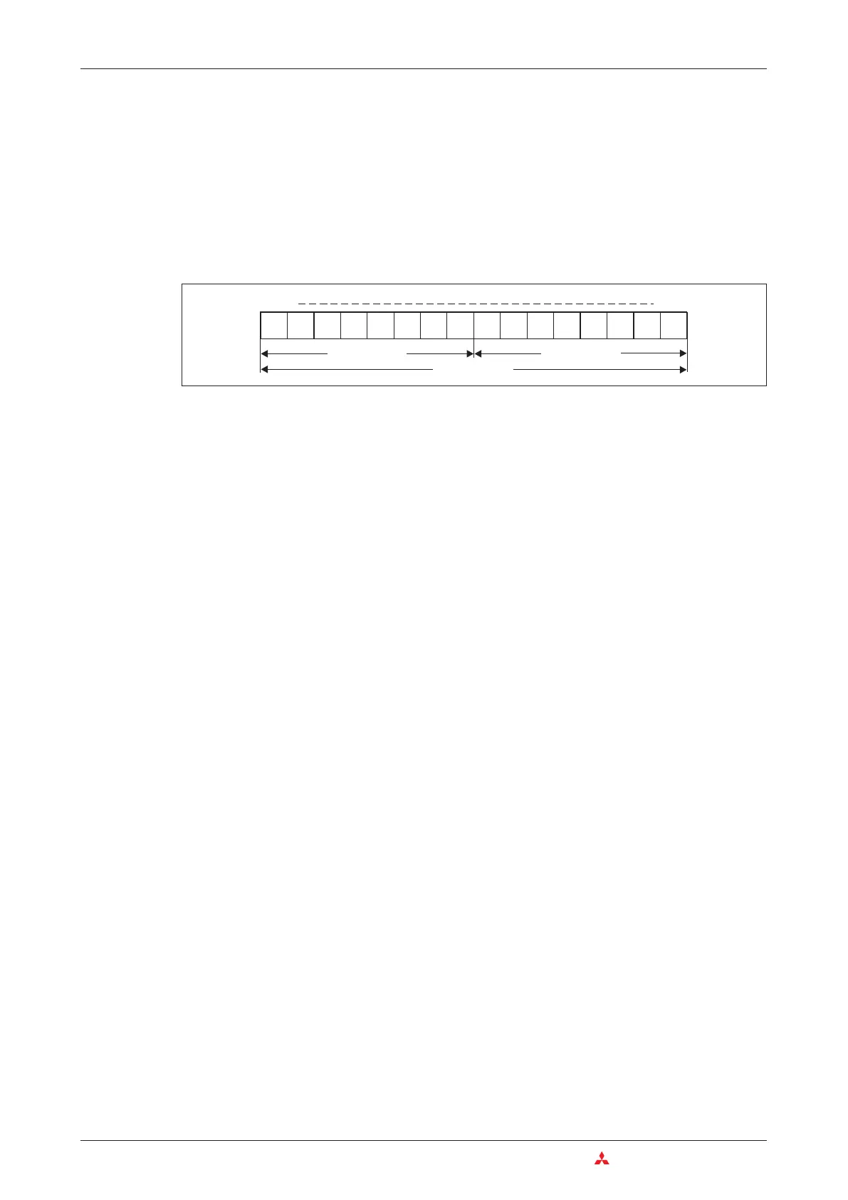
The next larger information units are the “byte”, which consists of 8 bits, and the “word”, which
consists of two bytes. In the MELSEC System Q range of PLCs the data registers are “word
devices”, which means that they can store 16-bit values.
Since a data register is 16 bits wide it can store signed values between -32,768 and +32,767
(see next chapter 4.3). When larger values need to be stored two words are combined to form a
32-bit long word, which can store signed values between -2,147,483,648 and +2,147,483,647.
4.3 Number Systems
The PLCs of the MELSEC System Q use several different number systems for inputting and
displaying values and for specifying device addresses.
Decimal numbers
The decimal number system is the system we use most commonly in everyday life. It is a “posi-
tional base 10” system, in which each digit (position) in a numeral is ten times the value of the
digit to its right. After the count reaches 9 in each position the count in the current position is
returned to 0 and the next position is incremented by 1 to indicate the next decade (9 à 10, 99
à 100, 199 à 1,000 etc).
Base: 10
Digits:0,1,2,3,4,5,6,7,8,9
In the MELSEC System Q family of PLCs decimal numbers are used for entering constants
and the setpoint values for timers and counters.Device addresses are also entered in decimal
format, with the exception of the addresses of inputs and outputs.
Binary numbers
Like all computers a PLC can only really distinguish between two states, ON/OFF or 0/1.These
“binary states” are stored in individual bits. When numbers need to be entered or displayed in
other formats the programming software automatically converts the binary numbers into the
other number systems.
Base: 2
Digits: 0 and 1
4–2 MITSUBISHI ELECTRIC
Bits, Bytes and Words An Introduction to Programming
0000000000 000
0
00
1 Byte 1 Byte
1 Word
Bit 15 Bit 0

Table of Contents

Other manuals for Mitsubishi MELSEC System Q

Question and Answer IconNeed help?

Do you have a question about the Mitsubishi MELSEC System Q and is the answer not in the manual?

Mitsubishi MELSEC System Q Specifications

General IconGeneral
CategoryProgrammable Logic Controller (PLC)
TypeModular
SeriesMELSEC
I/O CapacityUp to 4096 points
Programming LanguagesLadder Logic, Structured Text, Function Block Diagram, Instruction List, Sequential Function Chart
Communication ProtocolsEthernet, CC-Link
RedundancyAvailable in certain models
Power Supply24 V DC, 100-240 V AC (depending on the power supply module)
Operating Temperature0°C to 55°C
Storage Temperature-25°C to 75°C
Humidity5% to 95% (non-condensing)
Shock Resistance147 m/s2 acceleration, 3 times in each of the X, Y, and Z directions
CPU TypeVarious CPUs available (e.g., Q00, Q01, Q02, Q06, Q12, Q13, Q26, Q100, Q172, Q173)

Summary

2 Programmable Logic Controllers

3 The MELSEC System Q

3.1 System Configuration

Details the modular structure and components of the MELSEC System Q.

3.2 Base Units

Describes available base units for mounting MELSEC System Q modules.

3.3 Power Supply Modules

Explains the function and types of power supply modules for MELSEC System Q.

3.4 The CPU Modules

Introduces different types of CPU modules available for the MELSEC System Q.

3.5 Digital Input and Output Modules

Describes the types and functions of digital input and output modules.

3.5.1 Digital Input Modules

Explains the specifications and considerations for digital input modules.

3.5.2 Digital Output Modules

Details the types, advantages, and specifications of digital output modules.

3.6 Special Function Modules

Introduces various special function modules for MELSEC System Q automation.

3.6.1 Analog Modules

Explains analog input and output modules and selection criteria.

3.7 Networks and Network Modules

Covers networking concepts and modules for MELSEC System Q communication.

3.7.4 Network Modules

Explains ETHERNET and MELSECNET modules for system communication.

4 An Introduction to Programming

4.7 The Basic Instruction Set

Provides a reference to basic instructions used in MELSEC PLC programming.

4.8 Safety First!

Emphasizes crucial safety precautions when working with PLCs and systems.

4.9 Programming PLC Applications

Demonstrates PLC application development with a practical example.

4.9.1 A rolling shutter gate

Presents a detailed example of programming a rolling shutter gate control system.

4.9.2 Programming

Guides through the process of creating a new PLC project and assigning variables.

5 Devices in Detail

5.1 Inputs and Outputs

Explains how PLC inputs and outputs connect to the controlled process.

5.2 Relays

Details the function and types of relays (normal and latched) in PLC programs.

5.3 Timers

Describes programmable internal timers, their function, and types (low/high speed, retentive).

5.4 Counters

Explains internal counters for programming counting operations and their features.

5.5 Registers

Covers registers for storing measurements and calculation results (16-bit and 32-bit).

5.5.1 Data registers

Details data registers used for memory storage in PLC programs.

6 More Advanced Programming

6.1 Applied Instructions Reference

Provides a reference for advanced PLC instructions beyond basic logic.

6.2 Instructions for Moving Data

Explains instructions for moving data between registers and devices.

6.2.5 Exchanging data with special function modules

Details using FROM/TO instructions for data exchange with special function modules.

6.3 Compare Instructions

Explains instructions for comparing values (numerical, string) in PLC programs.

6.4 Math Instructions

Covers basic arithmetic operations like addition, subtraction, multiplication, and division.

Related product manuals