As you might expect, there is also a pulse-triggered version of the 32-bit DMOV instruction:
When relay M10 is set the contents of registers D10 and D11 are written to registers D610 and
D611.
NOTE In Ladder Diagram and the IEC instruction list 32-bit devices have to be declared as Global
Variables (see chapter 4.6.2). It is not possible to enter these devices directly.
6.2.2 Moving groups of bit devices
The previous section showed how you can use the MOV instruction to write constants or the
contents of data registers to other data registers. Consecutive sequences of relays and other
bit devices can also be used to store numerical values, and you can copy them as groups with
applied instructions. To do this you prefixing a “K” factor to the address of the first bit device,
specifying the number of devices you want to copy with the operation.
Bit devices are counted in groups of 4, so the K factor specifies the number of these groups of
4. K1 = 4 devices, K2 = 8 devices, K3 = 12 devices and so on.
For example, K2M0 specifies the 8 relays from M0 through M7. The supported range is K1 (4
devices) to K8 (32 devices).
Examples for addressing groups of bit devices:
–
K1X0: 4 inputs, start at X0 (X0 to X3)
–
K2X4: 8 inputs, start at X4 (X4 to X1B, hexadecimal notation)
–
K4M16: 16 relays, start at M16 (M16 to M31)
–
K3Y0: 12 outputs, start at Y0 (Y0 to Y1B, hexadecimal notation)
–
K8M0: 32 relays, start at M0 (M0 to M31)
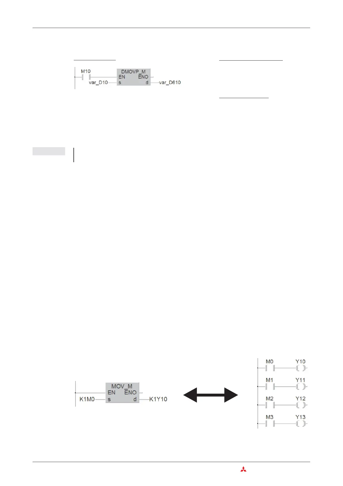
Addressing multiple bit devices with a single instruction makes programming quicker and pro
-
duces more compact programs. The following two examples both transfer the signal states of
relays M0 – M3 to outputs Y10 – Y13:
If the destination range is smaller than the source range the excess bits are simply ignored
(see the following illustration, top example). If the destination is larger than the source “0” is
6–14 MITSUBISHI ELECTRIC
Instructions for Moving Data More Advanced Programming
Ladder Diagram
MELSEC Instruction List
LD M10
DMOVP D10 D610
IEC
Instruction List
LD X1
DMOVP_M var_D10,var_D610

 Loading...


