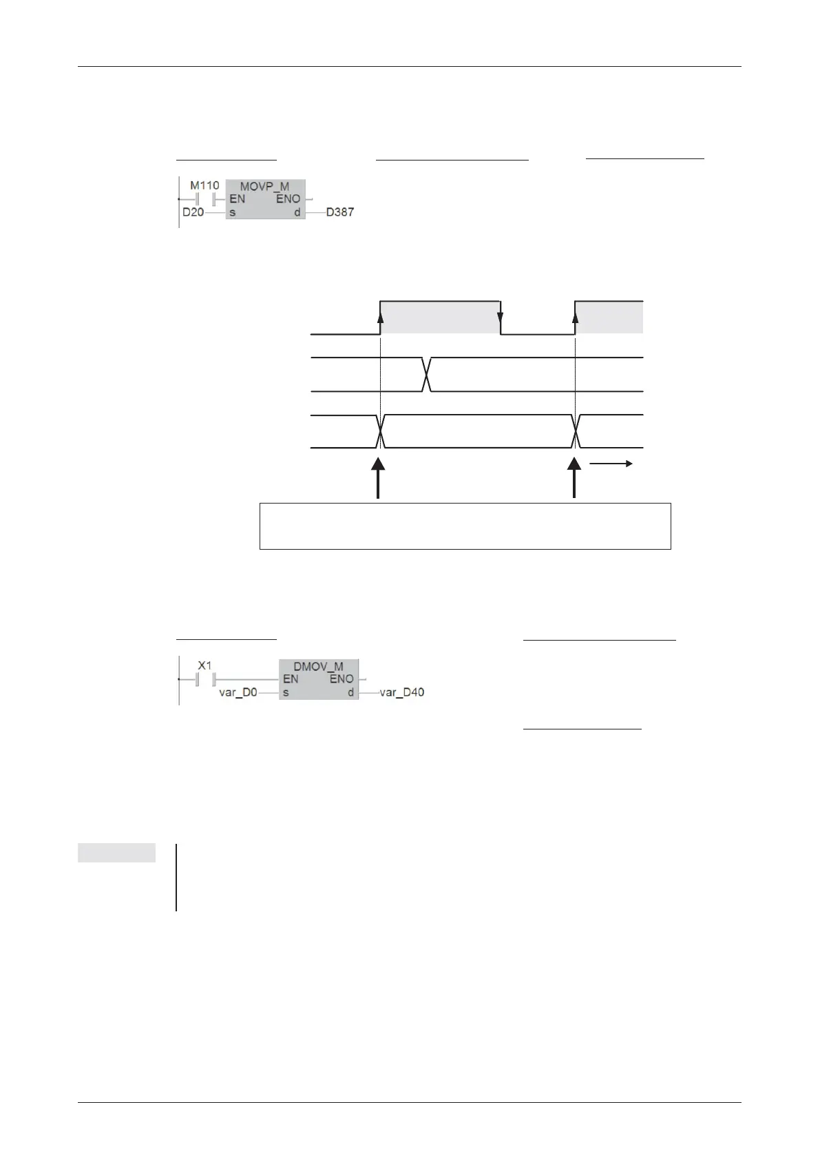
In the example below the contents of D20 are written to data register D387 when the state of
M110 changes from “0" to ”1".
After this single operation has been performed copying to register D387 stops, even if the
M110 remains set. The signal sequence illustrates this:
Moving 32-bit data
To move 32-bit data just prefix a D to the MOV instruction (DMOV):
When input X1 is on the contents of the data registers D0 and D1 is written to data registers
D40 and D41.(The contents of D0 is copied to D40 and the contents of D1 is copied to D41).
NOTE With GX IEC Developer it is not possible in Ladder Diagram and the IEC instruction list to de
-
fine 32-bit devices as input and output variables directly. These devices must be declared as
Global Variables (see chapter 4.6.2). In this example the identifiers var_D0 and var_D40
were chosen to point to this fact.
MELSEC System Q Beginners Manual 6 – 13
More Advanced Programming Instructions for Moving Data
D20
D387
M110
t
4700
4700
6800
3300
3300
The contents of the data source are only copied to the destina-
tion on the rising pulse of the input condition.
Ladder Diagram
MELSEC Instruction List
LD M110
MOVP D20
D387
IEC
Instruction List
LD M110
MOVP_M D20, D387
Ladder Diagram
MELSEC Instruction List
LD X1
DMOV D0 D40
IEC
Instruction List
LD X1
DMOV_M var_D0, varD40

 Loading...


