–
A photoelectric barrier (S7) must be installed to identify obstacles in the gateway.If it regis
-
ters an obstacle while the gate is closing the gate must open automatically.
–
Two limit switches must be installed to stop the gate motor when the gate reaches the fully
open (S3) and fully closed (S6) positions.
Assignment of the input and output signals
The task description clearly defines the number of inputs and outputs needed. The gate drive
motor is controlled with two outputs. The signals required are assigned to the PLC inputs and
outputs as follows:
4.9.2 Programming
Creating a new project
MELSEC System Q Beginners Manual 4 – 35
An Introduction to Programming Programming PLC Applications
Function Name Address Remarks
Inputs
STOP button S0 X0
Break contact (when the switch is opera
-
ted X0 = “0” and the gate stops)
OPEN key-operated switch
(outside)
S1 X1
Make contacts
OPEN button (inside) S2 X2
Upper limit switch (gate open) S3 X3
Break contact (X2 =”0” when the gate is
up and S3 is activated)
CLOSE button (inside) S4 X4
Make contacts
CLOSE button (outside) S5 X5
Lower limit switch (gate closed) S6 X6
Break contact (X6 = “0” when the gate is
down and S6 is activated)
Photoelectric barrier S7 X7
X7 is set to “1” when an obstacle is regis
-
tered
Outputs
Warning lamp H1 Y10 —
Motor contactor (motor reverse) K1 Y11 Reverse = OPEN gate
Motor contactor (motor forward) K2 Y12 Forward = CLOSE gate
Timer Delay for automatic close — T0 Time: 20 seconds
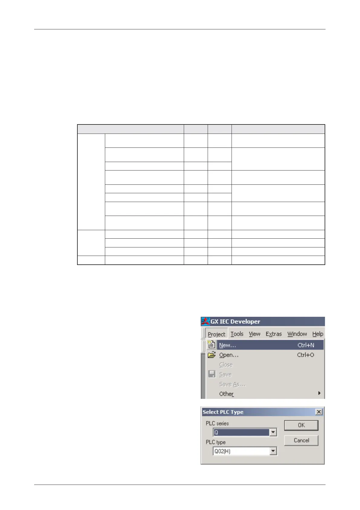
After the start of GX IEC Developer select
New
in the
Project
menu.
Choose the appropriate PLC type from the
selection.
Click on
OK
to confirm your selection

 Loading...


