3.2.2 Allocation of I/O Addresses
To address inputs and outputs of a PLC in the program they must be undisputed labeled.This is
done by assigning a number to each input and output: the I/O address (see also chapter 4.1).
These addresses are counted in hexadecimal numbers. (Please read more about different
number systems later in chapter 4.3.)
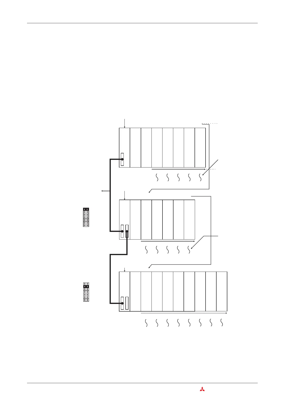
A CPU of the MELSEC System Q automatically recognises the slots available in main and
extension base units and assigns addresses to the inputs and outputs accordingly.
However, the assignment can also be done with the aid of the programming software. Thus
slots can be left empty or addresses can be reserved for future extensions.
The extension stage is set at the extension main unit with jumpers.
3–4 MITSUBISHI ELECTRIC
Base Units The MELSEC System Q
0
12
3
4
5
6
7
89
10
11 12
13
14
15 16
17
X00 X10 X20 Y40 Y50
X0F
X1F
X3F
Y4F
Y8F
90
B0 D0 YF0
100
AF CF EF YFF
10F
X110 X120
130 150 170
Y190 Y1A0 Y1B0
X11F X12F 14F
1
F1
FY1
F
Y1AF Y1BF
1
2
Extension cable
QB65B (4 slots are
occupied)
QB68B (8 slots are
occupied)
Power supply
CPU
Input module
16 input points
Input module
32 input points
Output module
16 output points
Output module
64 output points
Slot No.
Power supply
Special function
module, 32 I/O points
Special function
module, 32 I/O points
Special function
module, 32 I/O points
Output module
16 output points
Vacant
16 I/O points
The I/O numbers
are assigned
accordingtothe
number of physical
I/O on the relevant
slot.
Order of I/O
numbering
The slots are
numbered in
consecutive order.
The number of I/O
points for empty
slotsissetinthe
PLC parameters
(initial setting: 16)
Power supply
Input module
16 input points
Input module
16 input points
Special function
module, 32 I/O points
Special function
module, 32 I/O points
Output module
16 output points
Output module
16 output points
Output module
16 output points
Input module
16 input points
Special function
module, 32 I/O points
1st extension stage
2nd extension stage
QB35B (5 slots are occupied
by I/O modules)

 Loading...


