EasyManua.ls Logo

Mitsubishi MELSEC System Q User Manual

Mitsubishi MELSEC System Q
170 pages
To Next Page IconTo Next Page
To Previous Page IconTo Previous Page
Page #18 background imageLoading...
Page #18 background image
2.2 How PLCs Process Programs
A PLC performs its tasks by executing a program that is usually developed outside the control
-
ler and then transferred to the controller’s program memory. Before you start programming it is
useful to have a basic understanding of how PLCs process these programs.
A PLC program consists of a sequence of instructions that control the functions of the control
-
ler. The PLC executes these control instructions sequentially, i.e. one after another.The entire
program sequence is cyclical, which means that it is repeated in a continuous loop. The time
required for one program repetition is referred to as the program cycle time or period.
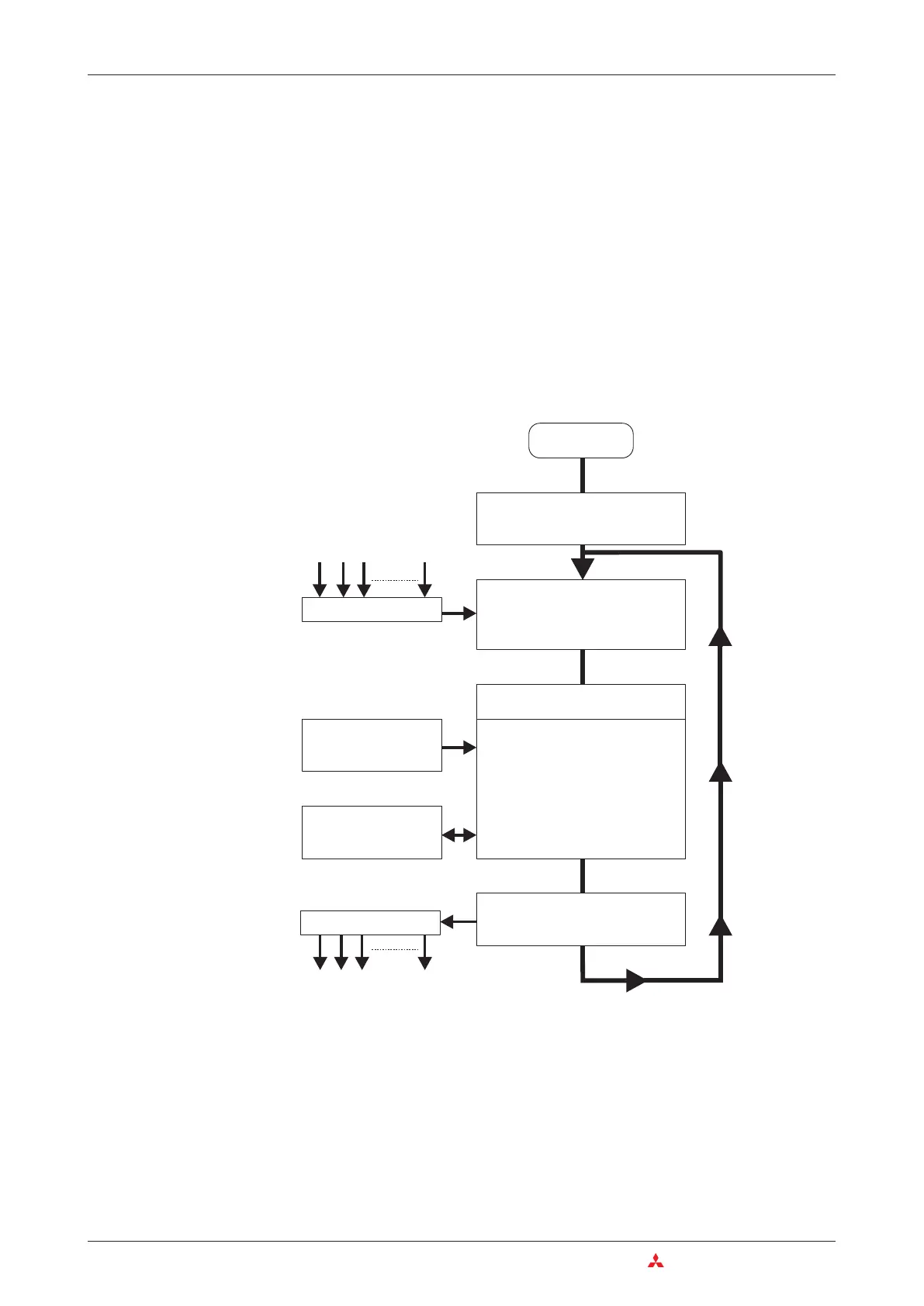
Process image processing
The program in the PLC is not executed directly on the inputs and outputs, but on a “process
image” of the inputs and outputs:
Input process image
At the beginning of each program cycle the system polls the signal states of the inputs and
stores them in a buffer, creating a “process image” of the inputs.
2–2 MITSUBISHI ELECTRIC
How PLCs Process Programs Programmable Logic Controllers
....
....
....
Switch on PLC
Delete output memory
Input terminals
Process image
of inputs
PLC program
Process image
of outputs
Output terminals
Transfer process image
to outputs
Instruction 1
Instruction 2
Instruction 3
Instruction n
Poll inputs and signal states
and save them in the process
image of the inputs
Input signals
Output signals

Table of Contents

Other manuals for Mitsubishi MELSEC System Q

Question and Answer IconNeed help?

Do you have a question about the Mitsubishi MELSEC System Q and is the answer not in the manual?

Mitsubishi MELSEC System Q Specifications

General IconGeneral
CategoryProgrammable Logic Controller (PLC)
TypeModular
SeriesMELSEC
I/O CapacityUp to 4096 points
Programming LanguagesLadder Logic, Structured Text, Function Block Diagram, Instruction List, Sequential Function Chart
Communication ProtocolsEthernet, CC-Link
RedundancyAvailable in certain models
Power Supply24 V DC, 100-240 V AC (depending on the power supply module)
Operating Temperature0°C to 55°C
Storage Temperature-25°C to 75°C
Humidity5% to 95% (non-condensing)
Shock Resistance147 m/s2 acceleration, 3 times in each of the X, Y, and Z directions
CPU TypeVarious CPUs available (e.g., Q00, Q01, Q02, Q06, Q12, Q13, Q26, Q100, Q172, Q173)

Summary

2 Programmable Logic Controllers

3 The MELSEC System Q

3.1 System Configuration

Details the modular structure and components of the MELSEC System Q.

3.2 Base Units

Describes available base units for mounting MELSEC System Q modules.

3.3 Power Supply Modules

Explains the function and types of power supply modules for MELSEC System Q.

3.4 The CPU Modules

Introduces different types of CPU modules available for the MELSEC System Q.

3.5 Digital Input and Output Modules

Describes the types and functions of digital input and output modules.

3.5.1 Digital Input Modules

Explains the specifications and considerations for digital input modules.

3.5.2 Digital Output Modules

Details the types, advantages, and specifications of digital output modules.

3.6 Special Function Modules

Introduces various special function modules for MELSEC System Q automation.

3.6.1 Analog Modules

Explains analog input and output modules and selection criteria.

3.7 Networks and Network Modules

Covers networking concepts and modules for MELSEC System Q communication.

3.7.4 Network Modules

Explains ETHERNET and MELSECNET modules for system communication.

4 An Introduction to Programming

4.7 The Basic Instruction Set

Provides a reference to basic instructions used in MELSEC PLC programming.

4.8 Safety First!

Emphasizes crucial safety precautions when working with PLCs and systems.

4.9 Programming PLC Applications

Demonstrates PLC application development with a practical example.

4.9.1 A rolling shutter gate

Presents a detailed example of programming a rolling shutter gate control system.

4.9.2 Programming

Guides through the process of creating a new PLC project and assigning variables.

5 Devices in Detail

5.1 Inputs and Outputs

Explains how PLC inputs and outputs connect to the controlled process.

5.2 Relays

Details the function and types of relays (normal and latched) in PLC programs.

5.3 Timers

Describes programmable internal timers, their function, and types (low/high speed, retentive).

5.4 Counters

Explains internal counters for programming counting operations and their features.

5.5 Registers

Covers registers for storing measurements and calculation results (16-bit and 32-bit).

5.5.1 Data registers

Details data registers used for memory storage in PLC programs.

6 More Advanced Programming

6.1 Applied Instructions Reference

Provides a reference for advanced PLC instructions beyond basic logic.

6.2 Instructions for Moving Data

Explains instructions for moving data between registers and devices.

6.2.5 Exchanging data with special function modules

Details using FROM/TO instructions for data exchange with special function modules.

6.3 Compare Instructions

Explains instructions for comparing values (numerical, string) in PLC programs.

6.4 Math Instructions

Covers basic arithmetic operations like addition, subtraction, multiplication, and division.

Related product manuals