EasyManua.ls Logo

Mitsubishi MELSEC System Q User Manual

Mitsubishi MELSEC System Q
170 pages
To Next Page IconTo Next Page
To Previous Page IconTo Previous Page
Page #118 background imageLoading...
Page #118 background image
5.3 Timers
When you are controlling processes you will often want to program a specific delay before
starting and stopping certain operations. In hard-wired controllers this is achieved with timer
relays. In PLCs this is achieved with programmable internal timers.
Timers are really just counters that count the PLCs internal clock signals (e.g. 0.1s pulses).
When the counter value reaches the setpoint value the timer’s output is switched on.
A timer is represented by four elements:
Set value (
TValue
)
Actual value (
TN
)
Timer coil (
TCoil
,
TC
)
Timer contact (
TS
)
All timers function as make delay switches and are activated with a “1” signal.To start and reset
timers you program them in the same way as outputs.You can poll the outputs of timers (TS) as
often as you like in your program.
The timer of the MELSEC System Q are distinguished between low speed and high speed
timer.With the GX IEC Developer the time base for the timer (i. e.the frequency of the clock sig
-
nal counted by the timer) can be set in the range from 1 ms to 1000 ms in the PLC parameters.
The initial value is 100 ms. The time base for high speed timer can be set in the range from
0.1 ms to 100 ms. The initial value in this case is 100 ms.
Whether a timer functions as low or as high speed timer is determined by the instruction which
starts the timer.
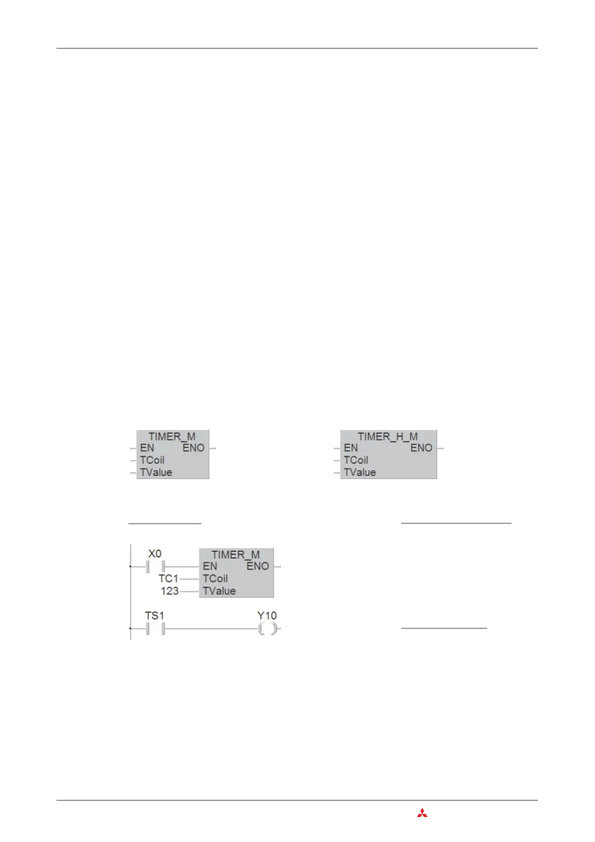
Example of a program using low speed timer
In the above example timer T1 is started when input X0 is switched on. The setpoint value is
123 x 100 ms = 12,3 s, so T200 switches on output Y10 after a delay of 1.23 s. The signal
sequence generated by the following program example is as follows:
5–6 MITSUBISHI ELECTRIC
Timers Devices in Detail
Ladder Diagram
MELSEC Instruction List
LD X0
OUT T1
K123
LD T1
OUT Y10
IEC Instruction List
LD X0
TIMER_M TC1, 123
LD TS1
ST Y10
As variable for the TCoil input of the
TIMER_M instruction the device address of
the timer is specified (in this example TC1).
Operation as low speed timer Operation as high speed timer

Table of Contents

Other manuals for Mitsubishi MELSEC System Q

Question and Answer IconNeed help?

Do you have a question about the Mitsubishi MELSEC System Q and is the answer not in the manual?

Mitsubishi MELSEC System Q Specifications

General IconGeneral
CategoryProgrammable Logic Controller (PLC)
TypeModular
SeriesMELSEC
I/O CapacityUp to 4096 points
Programming LanguagesLadder Logic, Structured Text, Function Block Diagram, Instruction List, Sequential Function Chart
Communication ProtocolsEthernet, CC-Link
RedundancyAvailable in certain models
Power Supply24 V DC, 100-240 V AC (depending on the power supply module)
Operating Temperature0°C to 55°C
Storage Temperature-25°C to 75°C
Humidity5% to 95% (non-condensing)
Shock Resistance147 m/s2 acceleration, 3 times in each of the X, Y, and Z directions
CPU TypeVarious CPUs available (e.g., Q00, Q01, Q02, Q06, Q12, Q13, Q26, Q100, Q172, Q173)

Summary

2 Programmable Logic Controllers

3 The MELSEC System Q

3.1 System Configuration

Details the modular structure and components of the MELSEC System Q.

3.2 Base Units

Describes available base units for mounting MELSEC System Q modules.

3.3 Power Supply Modules

Explains the function and types of power supply modules for MELSEC System Q.

3.4 The CPU Modules

Introduces different types of CPU modules available for the MELSEC System Q.

3.5 Digital Input and Output Modules

Describes the types and functions of digital input and output modules.

3.5.1 Digital Input Modules

Explains the specifications and considerations for digital input modules.

3.5.2 Digital Output Modules

Details the types, advantages, and specifications of digital output modules.

3.6 Special Function Modules

Introduces various special function modules for MELSEC System Q automation.

3.6.1 Analog Modules

Explains analog input and output modules and selection criteria.

3.7 Networks and Network Modules

Covers networking concepts and modules for MELSEC System Q communication.

3.7.4 Network Modules

Explains ETHERNET and MELSECNET modules for system communication.

4 An Introduction to Programming

4.7 The Basic Instruction Set

Provides a reference to basic instructions used in MELSEC PLC programming.

4.8 Safety First!

Emphasizes crucial safety precautions when working with PLCs and systems.

4.9 Programming PLC Applications

Demonstrates PLC application development with a practical example.

4.9.1 A rolling shutter gate

Presents a detailed example of programming a rolling shutter gate control system.

4.9.2 Programming

Guides through the process of creating a new PLC project and assigning variables.

5 Devices in Detail

5.1 Inputs and Outputs

Explains how PLC inputs and outputs connect to the controlled process.

5.2 Relays

Details the function and types of relays (normal and latched) in PLC programs.

5.3 Timers

Describes programmable internal timers, their function, and types (low/high speed, retentive).

5.4 Counters

Explains internal counters for programming counting operations and their features.

5.5 Registers

Covers registers for storing measurements and calculation results (16-bit and 32-bit).

5.5.1 Data registers

Details data registers used for memory storage in PLC programs.

6 More Advanced Programming

6.1 Applied Instructions Reference

Provides a reference for advanced PLC instructions beyond basic logic.

6.2 Instructions for Moving Data

Explains instructions for moving data between registers and devices.

6.2.5 Exchanging data with special function modules

Details using FROM/TO instructions for data exchange with special function modules.

6.3 Compare Instructions

Explains instructions for comparing values (numerical, string) in PLC programs.

6.4 Math Instructions

Covers basic arithmetic operations like addition, subtraction, multiplication, and division.

Related product manuals