EasyManua.ls Logo

Mitsubishi MELSEC System Q User Manual

Mitsubishi MELSEC System Q
170 pages
To Next Page IconTo Next Page
To Previous Page IconTo Previous Page
Page #119 background imageLoading...
Page #119 background image
You can also specify the timer setpoint value with a decimal value stored in a data register. See
section 5.7.1 for details.
Retentive timers
In addition to the normal timers described above the controllers of the MELSEC System Q also
have retentive timers that retain their current time counter value even if the device controlling
them is switched off.
The current timer counter value is stored in a memory that is retained even in the event of a
power failure.
The device identifier for retentive timer is "ST". Similar to "normal" timers, retentive timers can
be programmed as low speed or high speed timers.
NOTE When shipped, 2048 (2k) normal timers are set in the parameters of an PLC CPU and no re-
tentive timers. In order to use retentive timers, the number of these timers must be set in the
PLC parameters.
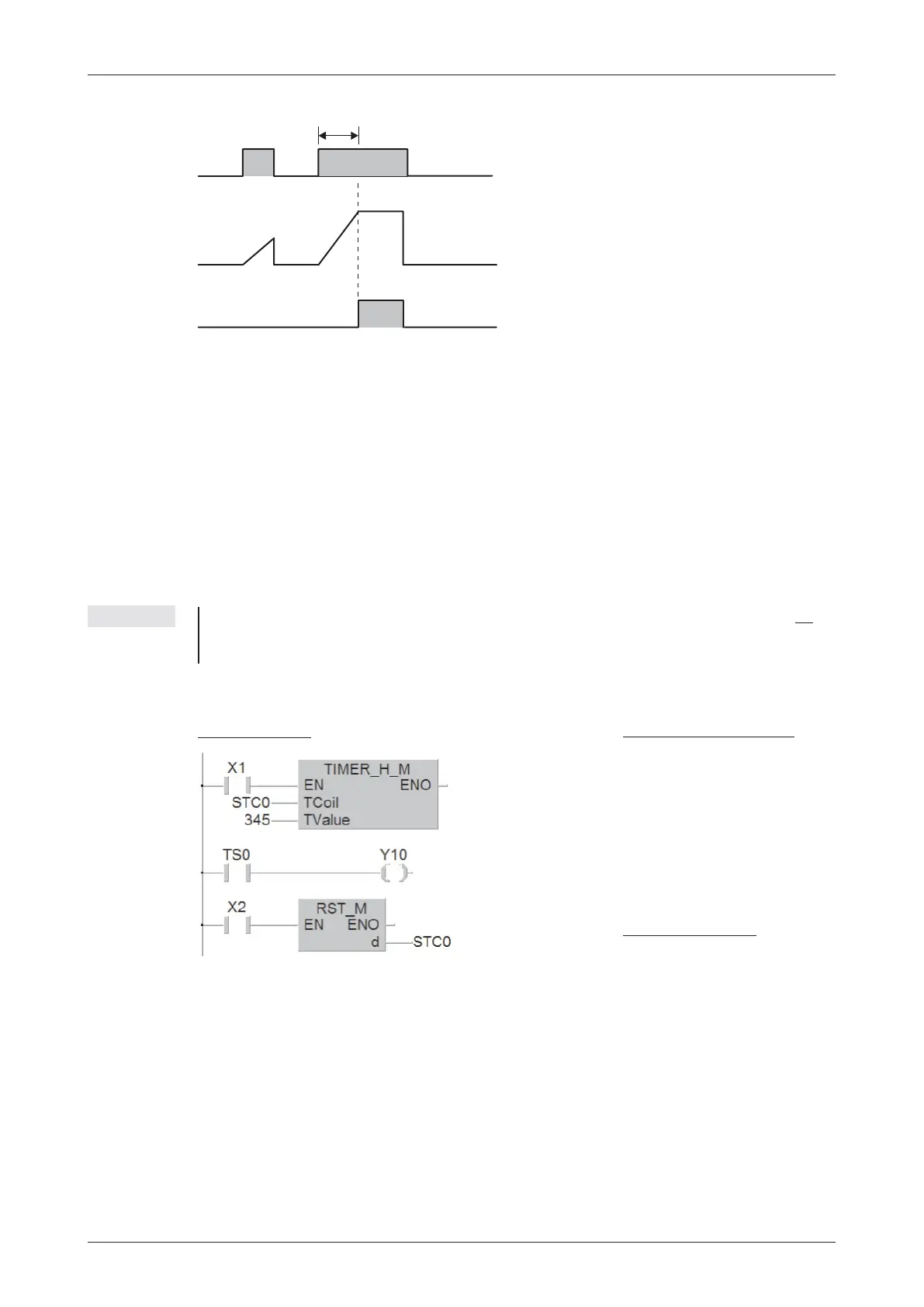
Example of a program using a retentive timer as high speed timer:
Timer T0 is started when input X1 is switched on. The setpoint value is 345 x 10ms = 3.45s.
When the setpoint value is reached T0 switches output Y10 on. Input X2 resets the timer and
switches its output off.
MELSEC System Q Beginners Manual 5 7
Devices in Detail Timers
The timer continues to count the internal
100ms pulses as long as X0 remains on.
When the setpoint value is reached the
output of T1 is switched on.
If input X0 or the power supply of the PLC
are switched off the timer is reset and its
output is also switched off.
Ladder Diagram
MELSEC Instruction List
LD X1
OUTH ST0
K345
LD ST0
OUT Y10
LD X2
RST ST0
IEC
Instruction List
LD X1
TIMER_H_M STC0, 345
LD STS0
OUT Y10
LD X2
RSTC0
X0
T1
Y10
12,3 s

Table of Contents

Other manuals for Mitsubishi MELSEC System Q

Question and Answer IconNeed help?

Do you have a question about the Mitsubishi MELSEC System Q and is the answer not in the manual?

Mitsubishi MELSEC System Q Specifications

General IconGeneral
CategoryProgrammable Logic Controller (PLC)
TypeModular
SeriesMELSEC
I/O CapacityUp to 4096 points
Programming LanguagesLadder Logic, Structured Text, Function Block Diagram, Instruction List, Sequential Function Chart
Communication ProtocolsEthernet, CC-Link
RedundancyAvailable in certain models
Power Supply24 V DC, 100-240 V AC (depending on the power supply module)
Operating Temperature0°C to 55°C
Storage Temperature-25°C to 75°C
Humidity5% to 95% (non-condensing)
Shock Resistance147 m/s2 acceleration, 3 times in each of the X, Y, and Z directions
CPU TypeVarious CPUs available (e.g., Q00, Q01, Q02, Q06, Q12, Q13, Q26, Q100, Q172, Q173)

Summary

2 Programmable Logic Controllers

3 The MELSEC System Q

3.1 System Configuration

Details the modular structure and components of the MELSEC System Q.

3.2 Base Units

Describes available base units for mounting MELSEC System Q modules.

3.3 Power Supply Modules

Explains the function and types of power supply modules for MELSEC System Q.

3.4 The CPU Modules

Introduces different types of CPU modules available for the MELSEC System Q.

3.5 Digital Input and Output Modules

Describes the types and functions of digital input and output modules.

3.5.1 Digital Input Modules

Explains the specifications and considerations for digital input modules.

3.5.2 Digital Output Modules

Details the types, advantages, and specifications of digital output modules.

3.6 Special Function Modules

Introduces various special function modules for MELSEC System Q automation.

3.6.1 Analog Modules

Explains analog input and output modules and selection criteria.

3.7 Networks and Network Modules

Covers networking concepts and modules for MELSEC System Q communication.

3.7.4 Network Modules

Explains ETHERNET and MELSECNET modules for system communication.

4 An Introduction to Programming

4.7 The Basic Instruction Set

Provides a reference to basic instructions used in MELSEC PLC programming.

4.8 Safety First!

Emphasizes crucial safety precautions when working with PLCs and systems.

4.9 Programming PLC Applications

Demonstrates PLC application development with a practical example.

4.9.1 A rolling shutter gate

Presents a detailed example of programming a rolling shutter gate control system.

4.9.2 Programming

Guides through the process of creating a new PLC project and assigning variables.

5 Devices in Detail

5.1 Inputs and Outputs

Explains how PLC inputs and outputs connect to the controlled process.

5.2 Relays

Details the function and types of relays (normal and latched) in PLC programs.

5.3 Timers

Describes programmable internal timers, their function, and types (low/high speed, retentive).

5.4 Counters

Explains internal counters for programming counting operations and their features.

5.5 Registers

Covers registers for storing measurements and calculation results (16-bit and 32-bit).

5.5.1 Data registers

Details data registers used for memory storage in PLC programs.

6 More Advanced Programming

6.1 Applied Instructions Reference

Provides a reference for advanced PLC instructions beyond basic logic.

6.2 Instructions for Moving Data

Explains instructions for moving data between registers and devices.

6.2.5 Exchanging data with special function modules

Details using FROM/TO instructions for data exchange with special function modules.

6.3 Compare Instructions

Explains instructions for comparing values (numerical, string) in PLC programs.

6.4 Math Instructions

Covers basic arithmetic operations like addition, subtraction, multiplication, and division.

Related product manuals