5.7.4 Clock signal generators
The controllers have special relays that make it very easy to program tasks requiring a regular
clock signal (for example for controlling a blinking error indicator light). Relay SM413 switches
on and off at 1-second intervals, for example. For full details on all special relays see the Pro
-
gramming Manual for the A/Q series and the MELSEC System Q, Art. no. 87431.
If you need a different clock frequency or different on and off times you can program your own
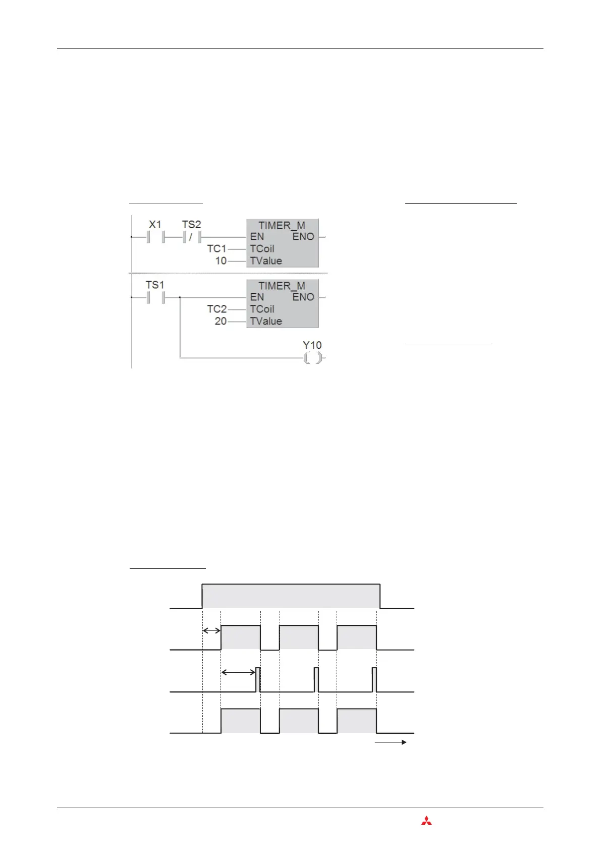
clock signal generator with two timers, like this:
Input X1 starts the clock generator. If you want, you can omit this input – then the clock genera-
tor is always on. In the program you could use the output of T1 to control a blinking warning
light. The on period is determined by T2, the off period by T1.
The output of timer T2 is only switched on for a single program cycle. This time is shown much
longer than it really is in the signal sequence illustration below. T2 switches T1 off and immedi
-
ately after this T2 itself is also switched off. In effect this means that the duration of the on
period is increased by the time that it takes to execute a program cycle. However, since the
cycle is only a few milliseconds long it can usually be ignored.
5–20 MITSUBISHI ELECTRIC
Programming Tips for Timers and Counters Devices in Detail
Ladder Diagram
MELSEC Instruction List
LD X1
ANI T2
OUT T1
K10
LD T1
OUT T2
K20
OUT Y10
IEC Instruction List
LD X1
ANDN TS2
TIMER_M TC1, 10
LD TS1
TIMER_M TC2, 20
ST Y10
T2
T1
Y10
X0
t1
t
OFF
ON
OFF
ON
0
1
0
1
t2
Signal sequence

 Loading...


