4.9.3 The Hardware
The rolling shutter gate can be implemented with the following components of the MELSEC
System Q:
쎲
Main base unit with at least two slots for I/O modules, e. g. Q33B
쎲
Power Supply Q62P
This power supply module provides 24 DC for the supply of sensors and indicator lamps.
Please note that this output can be loaded with a maximum current of 0.6 A.
쎲
CPU module (as required)*
쎲
1 Digital input module QX80 with 16 inputs (negative common)
쎲
1 Digital output module QY80 with 16 transistor outputs (source)
*
Of course it's a little bit exaggerated to use a PLC of the MELSEC System O solely for the control of a roller shutter
gate. The CPU would be unchallenged with this task. But as part of a complex application, e. g. for the control of a
production line, this application is conceivable.
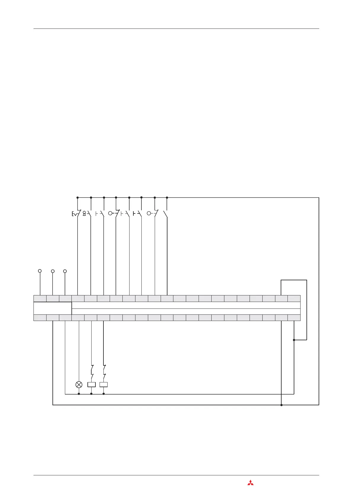
Connection of the PLC
A reference for the names of the electrical equipment and the function is shown on the next
page.
4–46 MITSUBISHI ELECTRIC
Programming PLC Applications An Introduction to Programming
PE
N
L1
Y10 Y11 Y12
X00 X01 X02 X03 X04 X05 X06 X07 X08 X09 X0A X0B X0C X0D X0E
X0F
COM
Y13 Y14 Y15 Y16 Y17 Y18 Y19 Y1A Y1B Y1C Y1D Y1E Y1F COM
LN
+24V
FG
24G
0V
S3
S4
S2
S5
S6
S7
S0
S1
K2
K1
S3
S6
K1 K2H1
Interlock by contactor
Deactivation by limit switches
Power supply
Digital Input Module
Digital Output Module

 Loading...


