5 Devices in Detail
The devices in PLCs are used directly in control program instructions. Their signal states can
be both read and changed by the PLC program. A device reference has two parts:
–
the device name and
–
the device address.
5.1 Inputs and Outputs
The PLC’s inputs and outputs connect it to the process that it is controlling. When an input is
polled by the PLC program the voltage on the input terminal of an input module is measured.
Since these inputs are digital they can only have two signal states, ON or OFF. When the volt
-
age at the input terminal reaches the rated voltage (e. g. 24V) the input is on (state “1”). If the
voltage is lower the input evaluates as off (signal state “0”).
In MELSEC PLCs the identifier “X” is used for inputs. The same input can be polled as often as
necessary in the same program.
NOTE The PLC cannot change the state of inputs.For example, it is not possible to execute an OUT
instruction on an input device.
If an output instruction is executed on an output the result of the current operation (the signal
state) is applied to the output terminal of an output module.If it is a relay output the relay closes
(all relays have make contacts). If it is a transistor output the transistor makes the connection
and activates the connected circuit.
The identifier for output devices is “Y”. Outputs can be used in logic operation instructions as
well as with output instructions.However, it is important to remember that you can never use an
output instruction on the same output more than once (see also section 4.7.2).
MELSEC System Q Beginners Manual 5 – 1
Devices in Detail Inputs and Outputs
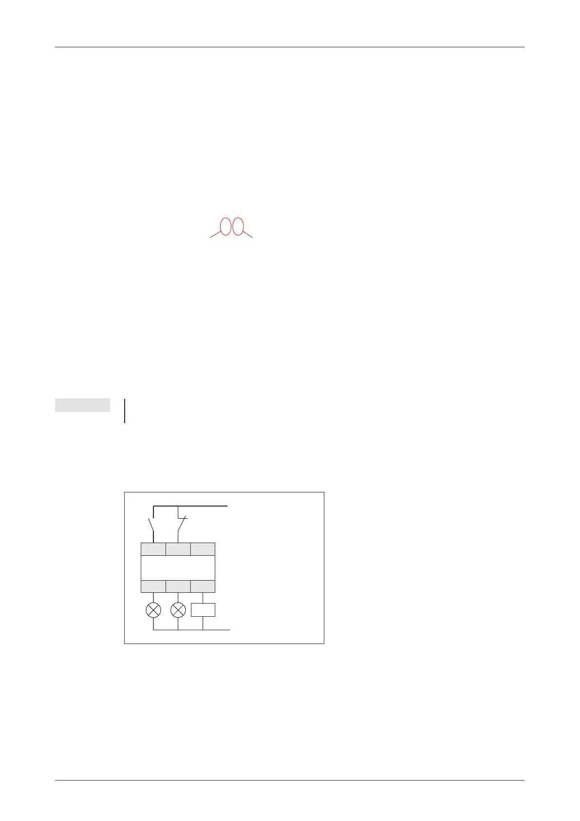
X000 X001
Y010 Y011
X002
Y012
The illustration on the left shows an example
of how you can connect switches to the
inputs and lamps and contactors to the out
-
puts of a MELSEC PLC.
Input module
Output module
CPU
X0
Device addressDevice name
Example of a device reference (e.g. input 0):

 Loading...


