6.2.5 Exchanging data with special function modules
You can supplement the controller’s functions by adding so-called “special function modules” –
for example for reading analog signals for currents and voltages, for controlling temperatures
and for communicating with external equipment.
Each special function module has a memory range assigned as a buffer for temporary storage
of data, such as analog measurement values or received data. The PLC CPU can access this
buffer and both read the stored values from it and write new values to it, which the module can
then process (settings for the module’s functions, data for transmission etc).
In addition to the buffer memory special function modules are equipped with digital inputs and
outputs.These I/O signals are used e. g. for exchanging status signals between the PLC CPU
and the special function module.The digital I/Os of the special function modules do not require
special instructions; these inputs and outputs are handled in exactly the same way as those in
digital I/O modules. Communication between the PLC CPU and the buffer memory of special
function modules however is performed with two special applied instructions: the FROM and
TO instructions.
The following information is required when you use the FROM and TO instructions:
–
The special function module to be read from or written to
–
The address of the first buffer memory cell to be read from or written to
–
The number of buffer memory cells to be read from or written to
–
The location in the PLC CPU where the data from the module is to be stored or containing
the data to be written to the module
6–18 MITSUBISHI ELECTRIC
Instructions for Moving Data More Advanced Programming
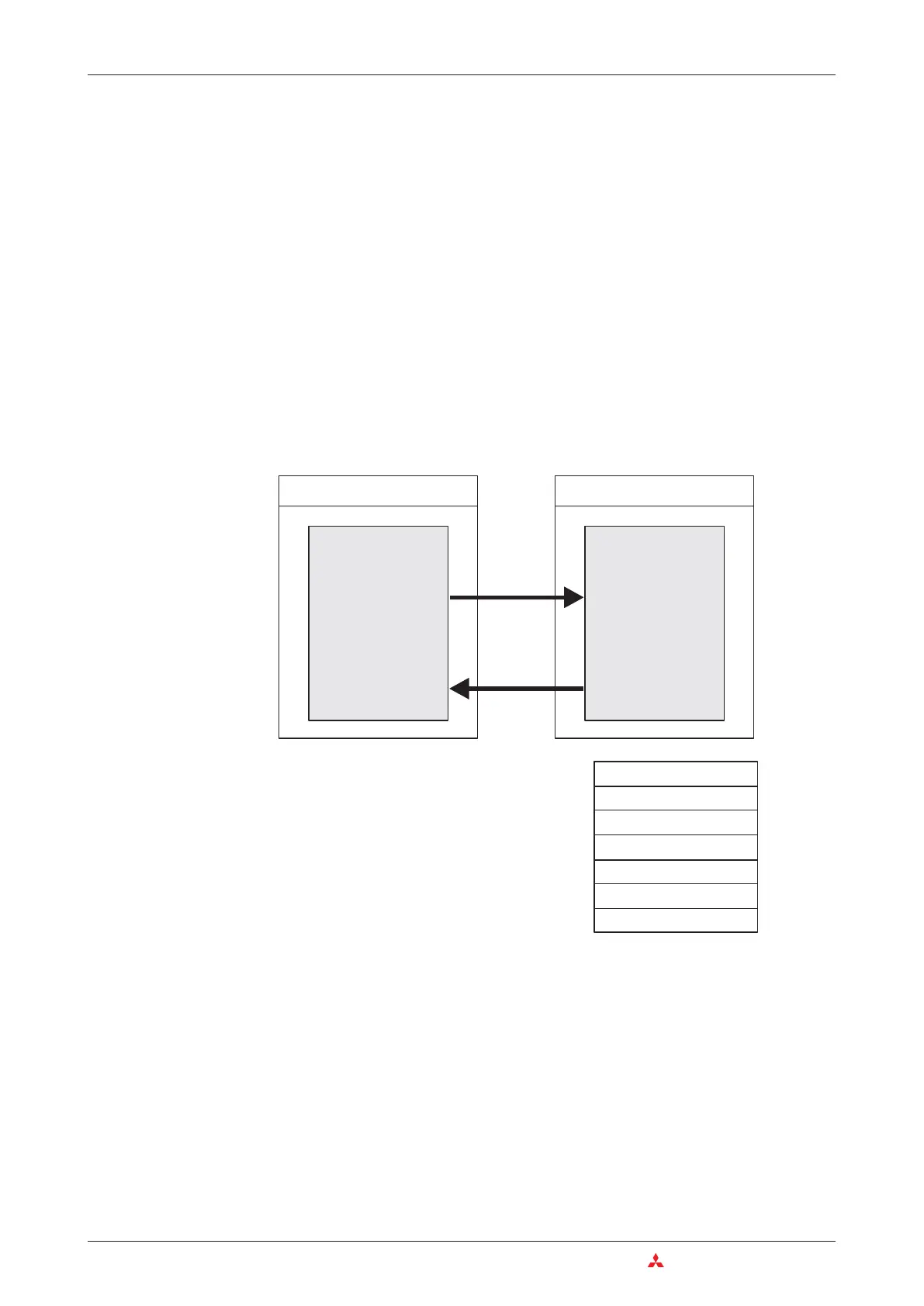
PLC CPU
Special function module
Buffer memory
Device memory
TO
FROM
The buffer memory can have up to 32,767 indi
-
vidual addressable memory cells, each of
which can store 16 bits of data. The functions of
the buffer memory cells depends on the indi
-
vidual special function module – see the mod
-
ule’s documentation for details.
Buffer memory address 0
Buffer memory address 1
Buffer memory address 2
Buffer memory address n
Buffer memory address n-1
:
:

 Loading...


