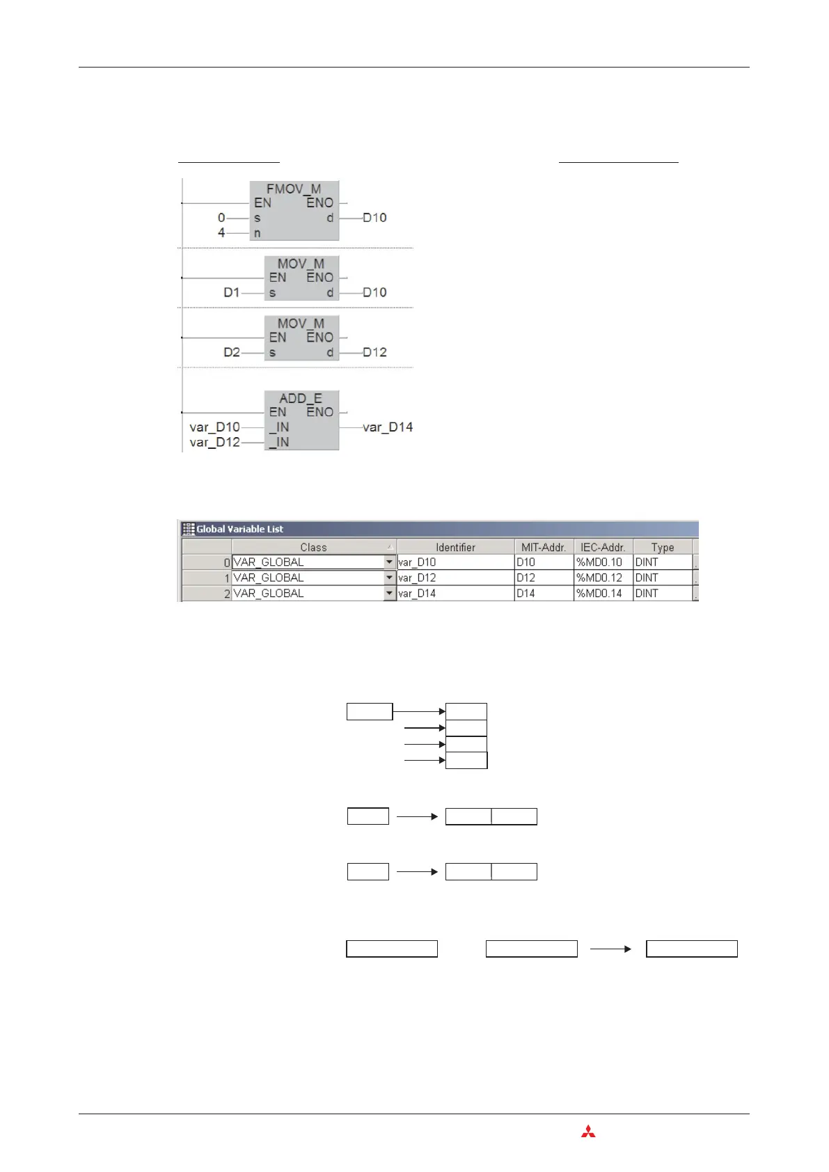
One possible solution is to copy the values to be added into 32-bit variables before the addition.
The addition is then performed with these 32-bit variables.
Since it is not possible to define 32-bit devices directly as input and output variables of an ADD
instruction a declaration as Global Variables is necessary:
The names for the variables (
Identifiers
) can be chosen freely. For a better understanding the
device addresses are used in this example.
With the values given above the contents of the data registers are changed during execution of
the instruction as follows:
Double word register D14 contains the correct result of the addition.
6–26 MITSUBISHI ELECTRIC
Math Instructions More Advanced Programming
Ladder Diagram
IEC Instruction List
LD TRUE
FMOV_M 0, 4, D10
LD TRUE
MOV_M D1, D10
LD TRUE
MOV_M D2, D12
LD var_D10
ADD var_D12
ST var_D14
Clear D10 to D13
Copy contents of D1 to D10
Copy contents of D2 to D12
Add contents of D11/D10 and
D13/D12, store result to
D15/D14
32700
D10
+
D 11
100
D12D 13
32800
D14D 15
100
D 2
100
D12D 13
0
32700
D1
32700
D10D 11
0
D 10
D 11
D 12
D 13
0
0
0
0
0
FMOV_M
MOV_M
MOV_M
ADD_E

 Loading...


