EasyManua.ls Logo

Mitsubishi MELSEC System Q User Manual

Mitsubishi MELSEC System Q
170 pages
To Next Page IconTo Next Page
To Previous Page IconTo Previous Page
Page #138 background imageLoading...
Page #138 background image
*
It is not possible to program the instructions FCALL, ECALL and EFCALL with the GX IEC Developer.
6–6 MITSUBISHI ELECTRIC
Applied Instructions Reference More Advanced Programming
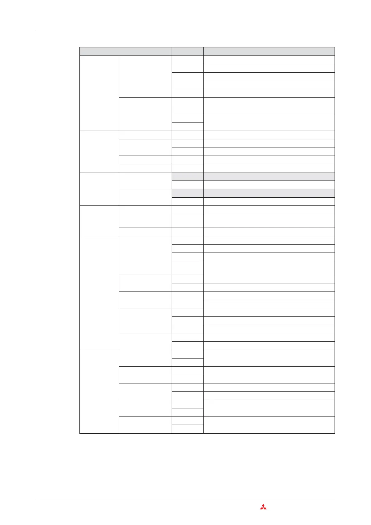
Category Instruction Function
Structured
program
instructions
Subroutine programs
CALL
Subroutine program call
RET
End of subroutine
FCALL*
Reset outputs in subroutines
ECALL*
Calling a subroutine program in a program file
EFCALL*
Reset outputs in subroutine programs in program files
Index qualification
IX
Index qualification of an entire program parts
IXEND
IXDEV
Store indexed device numbers in an index qualification
list
IXSET
Data table
operation
instructions
Write data
FIFW
Write data to a data table
Read data
FIFR
Read data entered first from data table
FPOP
Read data entered last from data table
Delete data
FDEL
Delete specified data blocks from data table
Insert data
FINS
Insert specified data blocks in data table
Buffer memory
access instruc
-
tions
Read
FROM
Read 16-bit data from special function module
DFRO
Read 32-bit data from special function module
Write
TO
Write 16-bit data to special function module
DTO
Write 32-bit data to special function module
Display
instructions
ASCII character
output
PR
Output of an ASCII character string to a peripheral device
PRC
Output of a comment (in ASCII code) to a peripheral
device
Clear display
LEDR
Reset annunciators and LED display
Failure
diagnosis and
debugging
Failure check
CHKST
Start instruction for the CHK instruction
CHK
Failure check
CHKCIR
Generate check circuits for the CHK instruction
CHKEND
End instruction for a program part with generated check
circuits
Store device status
SLT
Set status latch (Store device status)
SLTR
Reset status latch (clear device status)
Sampling trace
STRA
Set sampling trace
STRAR
Reset sampling trace
Program trace
PTRA
Set program trace
PTRAR
Reset program trace
PTRAEXE
Execute program trace
Trace
TRACE
Set trace
TRACER
Clear data stored by the trace instruction
Character
string process
-
ing instructions
Binary ->
Decimal (ASCII)
BINDA
Convert 16-/32-bit binary data into decimal values in
ASCII code
DBINDA
Binary ->
Hexadecimal (ASCII)
BINHA
Convert 16-/32-bit binary data into hexadecimal values in
ASCII code
DBINHA
BCD -> ASCII
BCDDA
Convert 4-digit BCD data into ASCII-Code
DBCDDA
Convert 8-digit BCD data into ASCII-Code
Decimal (ASCII) ->
Binary
DABIN
Convert decimal ASCII into 16-/32-bit binary data
DDABIN
Hexadecimal (ASCII)
-> Binary
HABIN
Convert decimal ASCII into 16-/32-bit binary data
DHABIN

Table of Contents

Other manuals for Mitsubishi MELSEC System Q

Question and Answer IconNeed help?

Do you have a question about the Mitsubishi MELSEC System Q and is the answer not in the manual?

Mitsubishi MELSEC System Q Specifications

General IconGeneral
CategoryProgrammable Logic Controller (PLC)
TypeModular
SeriesMELSEC
I/O CapacityUp to 4096 points
Programming LanguagesLadder Logic, Structured Text, Function Block Diagram, Instruction List, Sequential Function Chart
Communication ProtocolsEthernet, CC-Link
RedundancyAvailable in certain models
Power Supply24 V DC, 100-240 V AC (depending on the power supply module)
Operating Temperature0°C to 55°C
Storage Temperature-25°C to 75°C
Humidity5% to 95% (non-condensing)
Shock Resistance147 m/s2 acceleration, 3 times in each of the X, Y, and Z directions
CPU TypeVarious CPUs available (e.g., Q00, Q01, Q02, Q06, Q12, Q13, Q26, Q100, Q172, Q173)

Summary

2 Programmable Logic Controllers

3 The MELSEC System Q

3.1 System Configuration

Details the modular structure and components of the MELSEC System Q.

3.2 Base Units

Describes available base units for mounting MELSEC System Q modules.

3.3 Power Supply Modules

Explains the function and types of power supply modules for MELSEC System Q.

3.4 The CPU Modules

Introduces different types of CPU modules available for the MELSEC System Q.

3.5 Digital Input and Output Modules

Describes the types and functions of digital input and output modules.

3.5.1 Digital Input Modules

Explains the specifications and considerations for digital input modules.

3.5.2 Digital Output Modules

Details the types, advantages, and specifications of digital output modules.

3.6 Special Function Modules

Introduces various special function modules for MELSEC System Q automation.

3.6.1 Analog Modules

Explains analog input and output modules and selection criteria.

3.7 Networks and Network Modules

Covers networking concepts and modules for MELSEC System Q communication.

3.7.4 Network Modules

Explains ETHERNET and MELSECNET modules for system communication.

4 An Introduction to Programming

4.7 The Basic Instruction Set

Provides a reference to basic instructions used in MELSEC PLC programming.

4.8 Safety First!

Emphasizes crucial safety precautions when working with PLCs and systems.

4.9 Programming PLC Applications

Demonstrates PLC application development with a practical example.

4.9.1 A rolling shutter gate

Presents a detailed example of programming a rolling shutter gate control system.

4.9.2 Programming

Guides through the process of creating a new PLC project and assigning variables.

5 Devices in Detail

5.1 Inputs and Outputs

Explains how PLC inputs and outputs connect to the controlled process.

5.2 Relays

Details the function and types of relays (normal and latched) in PLC programs.

5.3 Timers

Describes programmable internal timers, their function, and types (low/high speed, retentive).

5.4 Counters

Explains internal counters for programming counting operations and their features.

5.5 Registers

Covers registers for storing measurements and calculation results (16-bit and 32-bit).

5.5.1 Data registers

Details data registers used for memory storage in PLC programs.

6 More Advanced Programming

6.1 Applied Instructions Reference

Provides a reference for advanced PLC instructions beyond basic logic.

6.2 Instructions for Moving Data

Explains instructions for moving data between registers and devices.

6.2.5 Exchanging data with special function modules

Details using FROM/TO instructions for data exchange with special function modules.

6.3 Compare Instructions

Explains instructions for comparing values (numerical, string) in PLC programs.

6.4 Math Instructions

Covers basic arithmetic operations like addition, subtraction, multiplication, and division.

Related product manuals